Incredibly frustrated at this point-
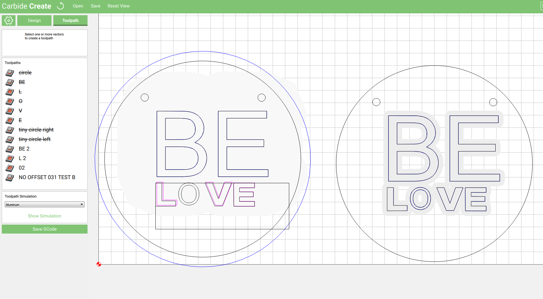
trying to engrave the text BE LOVE- the word BE is actual text and I’m using ‘no offset’ which seems to be recognized by CC (even though it does not show in the simulation) so I think I might be ok with that portion. The word LOVE is comprised of shapes and the letter O is an actual font letter (longish story on why I’ve done it that way) I’m trying to to a pocket for all portions of the LOVE section and CC does not recognize that. when I initially ran it it only did my circle cut out then made me change the bit to the vee bit I have selected for the engraving then plunged to the surface of the material after measuring the tool and the job ended with no engraving.
What I’ve attached still has my original toolpaths- they might be disabled now that I’ve been messing with this but they were not when I ran the job.
Please any help or suggestions are appreciated- I started trying to run this sample job when I got home from dropping my kids off at school and now i have to pick them up and I still have no sample:tired_face:belove frustration maximized.c2d (169.1 KB)
It has been 30 minutes and nobody has answered you so I will tell you my story. I have had very poor experience getting carbide create to engrave imported shapes. So when I need to engrave something that is not straightforward letters, I go to fusion 360 and create my engraving program GCode from there . I hope somebody has an easier answer for you, but there may not be one
This should be straight-forward to make — I assume that what you want is:
two drilled holes to fasten the piece in place and to allow for a cord to be passed through
text which will be V-engraved
an outer perimeter which will be cut out to separate the piece from the stock.
Okay, assuming the 1/2" x 1/2" information is correct, this should be pretty straight-forward:
launch Carbide Create
initial setup — machine, material, &c. — I’d set this for a 1" x 1" blank so as to allow for easier zooming, material thickness was set at 1/8" (3.175mm) (as opposed to the less than 1mm of the sample file which is a blank thin enough I’d worry about the edge cutting a person, or possibly being carved through when V-carving)
create a circle, set it to begin at 0.125" and 0.125" and be 0.75" in diameter (you’ll want your blank to be larger to accommodate clamps, and I found the 0.5" diameter a bit crowded w/ the two holes)
create a second circle, since Carbide Create doesn’t have a drill function, make it large enough that it will be possible to pocket it out, assuming a 1/16" endmill, we use the appropriate radius, multiply it by 1.05 to get the needed 10% fudge factor and round up: 0.066" radius
duplicate that circle (control c) and place the two appropriately
set the text — note that you will have to manually adjust the placement of each bit of text as it’s made so that it will be visible / selectable — note that for the text, so as to give the smaller text the same visual weight as the larger, I set the former in bold.
adjust everything as necessary
set CAM for three operations:
select the two small circles and Drill w/ a pocket contour
select the text and do a V-carve
select the outer circle and do a contour along the outside to cut things out
When you actually cut this out, I’d suggest putting plastic or aluminum screws down through the two holes.
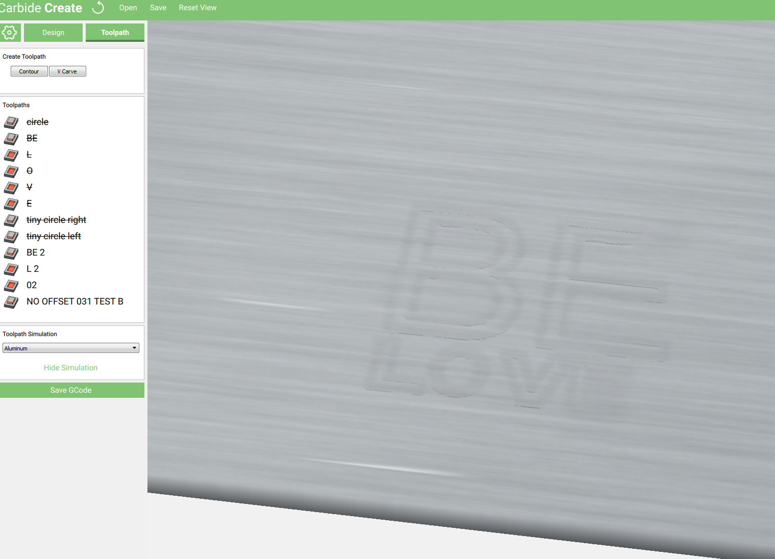
The engraved text seems to be too small for the preview to show well, and I’m at work so can’t try it out.
Thank you for looking at this Will but unfortunately changing the design is not an option- this is a client’s design and the weight and look of the text is important to her and the brand- a reason why I’m about to swear off all custom work!
I’ve been able to get smaller text working recently but it was all with no offsets, I didn’t need to do any pockets- I guess that’s the problem.
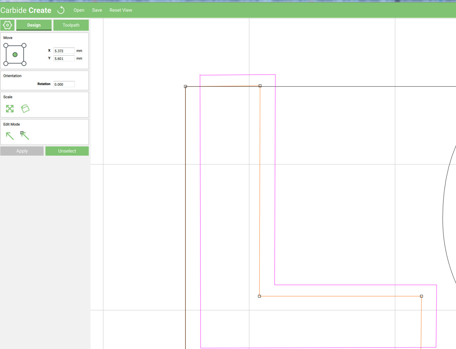
I opened your file and took a look, a few minor changes is all that’s needed.
The purple lines means its an open line - best if they are closed - So I traced over top of the purple leters and made sure to snap the end of the line to the beginning
thanks Apollo for your time and looking at this. I’m just now getting some free time to spend on this and tweak it to what I need- kids are finally asleep wahoo! I’m sure I’ll have more questions- just wanted to tell you how much I appreciate your response.
Thanks Rich- Apollo gave me some pointers and I’ll try to make it work for now but I’m going to look into fusion 360- its adobe right? which means its probably $$$ Such a huge learning curve for me- I thought I’d be able to do basic shape cut outs and simple engraving without much issue but that has proven to be a big miscalculation on my part! I’m going to put out a request for someone that I can pay to generate g-code on a few simple projects that I really need to get moving on- if you have a suggestion let me know. Thanks for your reply- I really appreciate it!
I think there was some misunderstanding. First, Fusion360 is free for hobby/education/small businesses, but I didn’t recommend a 3D software to start. A easy 2D (Autocad clone (I use DraftSight) to create easy 2D geometry (that’s not easy to create in Carbide Create), then import it into CC and then create my GCode from there.
Ahh, ok I see. Thank you! I was pretty frazzled today so I think that’s why I missed that some how the Fusion 360 stuck in my head. I use illustrator on a daily basis to lay out designs just to make sure I have the right proportions and to communicate with my clients, do you know if I can use that? or would something like the draftsight you use be better? Forgive the massive amount of questions, I’m just champing at the bit to make some progress here and I feel like I’ve I’ve watched so many videos and read so much I’m just a little lost.
Belike Illustrator is part of your problem, since it allows one to develop bad habits doing Bézier curves — unfortunately Silicon Publishing seems to have withdrawn their macro for directly creating G-code from w/in InDesign.
I really believe that you need to just grasp some basic terminology and learn to understand the difference between pocketing and profiles and that it’s pretty rare to need to follow an outline path for text.
just wanted to thank you again for your help- this worked! And I think my biggest problem was that the shapes weren’t snapped closed and I didn’t realize that. Thanks so much!

 Such a huge learning curve for me- I thought I’d be able to do basic shape cut outs and simple engraving without much issue but that has proven to be a big miscalculation on my part! I’m going to put out a request for someone that I can pay to generate g-code on a few simple projects that I really need to get moving on- if you have a suggestion let me know. Thanks for your reply- I really appreciate it!