Hi Will, I know this is an old post. The link is dead now to “blockscad3d.com”. Any chance the plans are somewhere else? I’d love to do a box like this!
Hi Jarret, I can’t seem to find Will’s post. Can you provide the link, please? Thanks! Roy
All of my BlockSCAD stuff should be at:
https://www.blockscad3d.com/community/users/67750#/?_k=rp9xuf
for boxes, most of them are on CutRocket:
https://cutrocket.com/u/WillAdams
and/or written up at:
If you’ll let me know which one it is, and what dimensions you want the box to be, and what features you want it to have I can do a custom file for you.
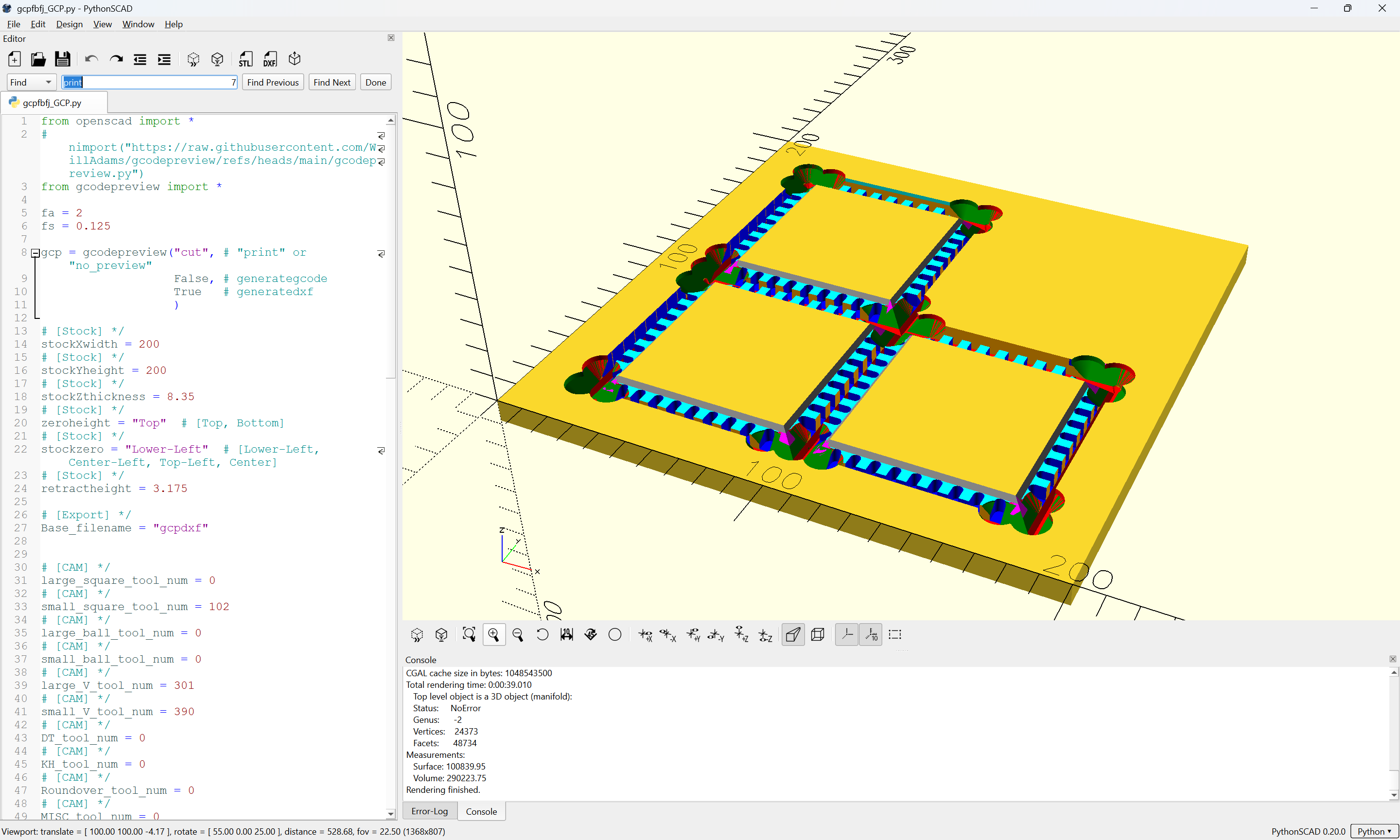
Note that my preferred joinery technique now is included in my personal project:
and allows one to define full-blind box joints:
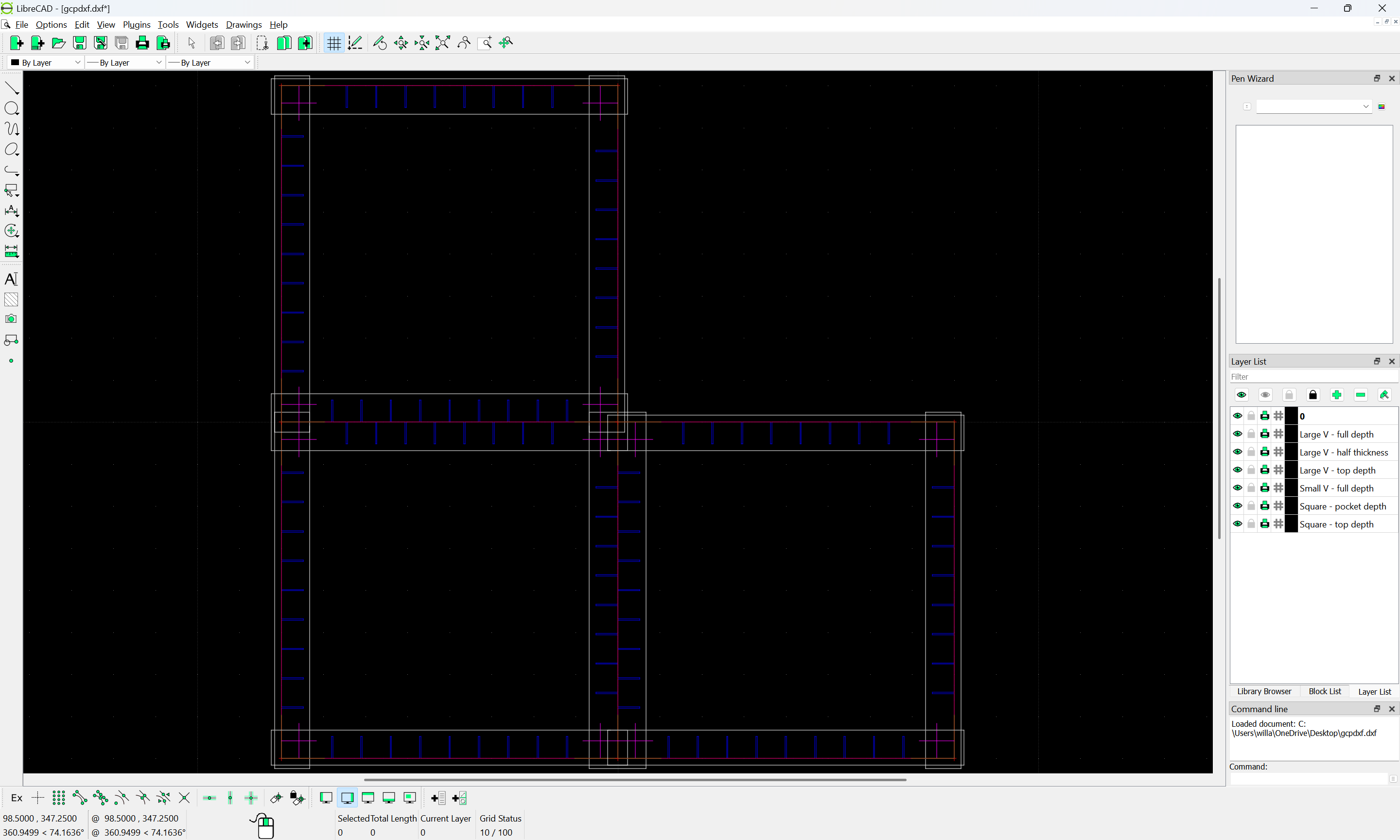
which may then be exported to a DXF w/ layers:
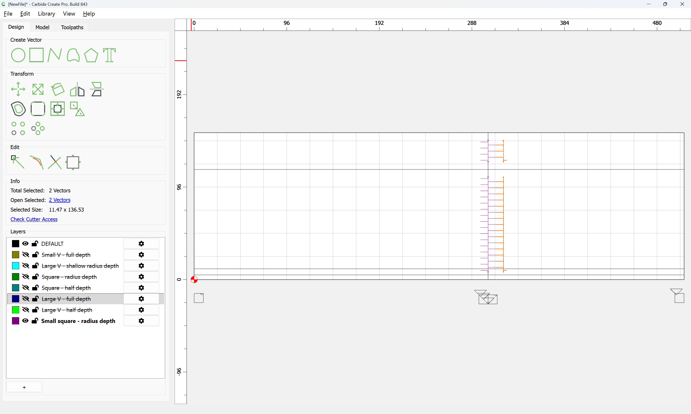
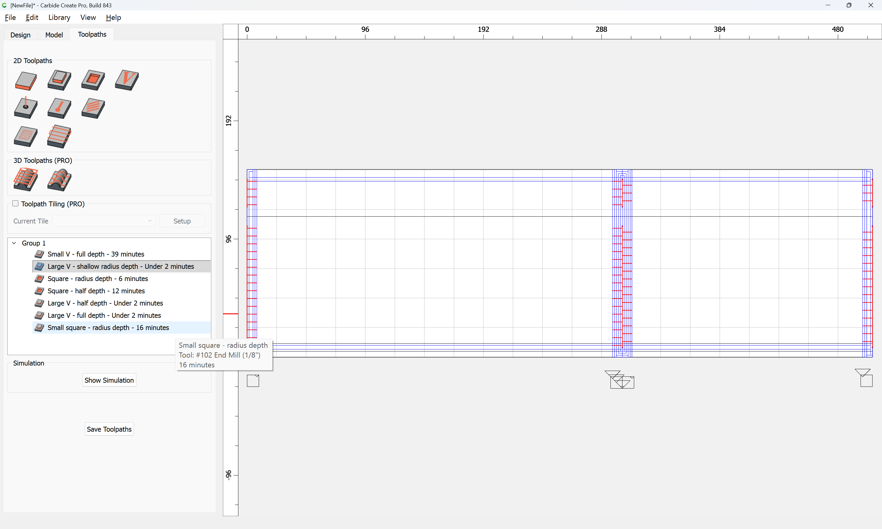
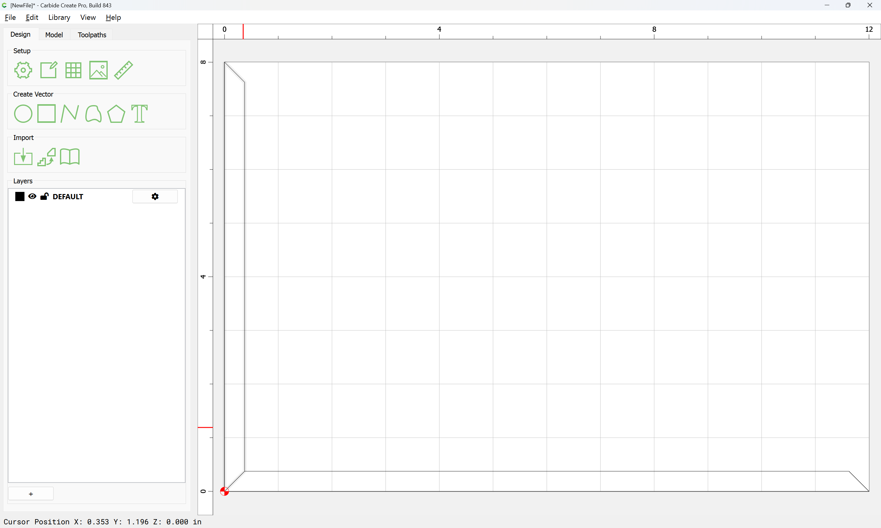
which when imported into Carbide Create:
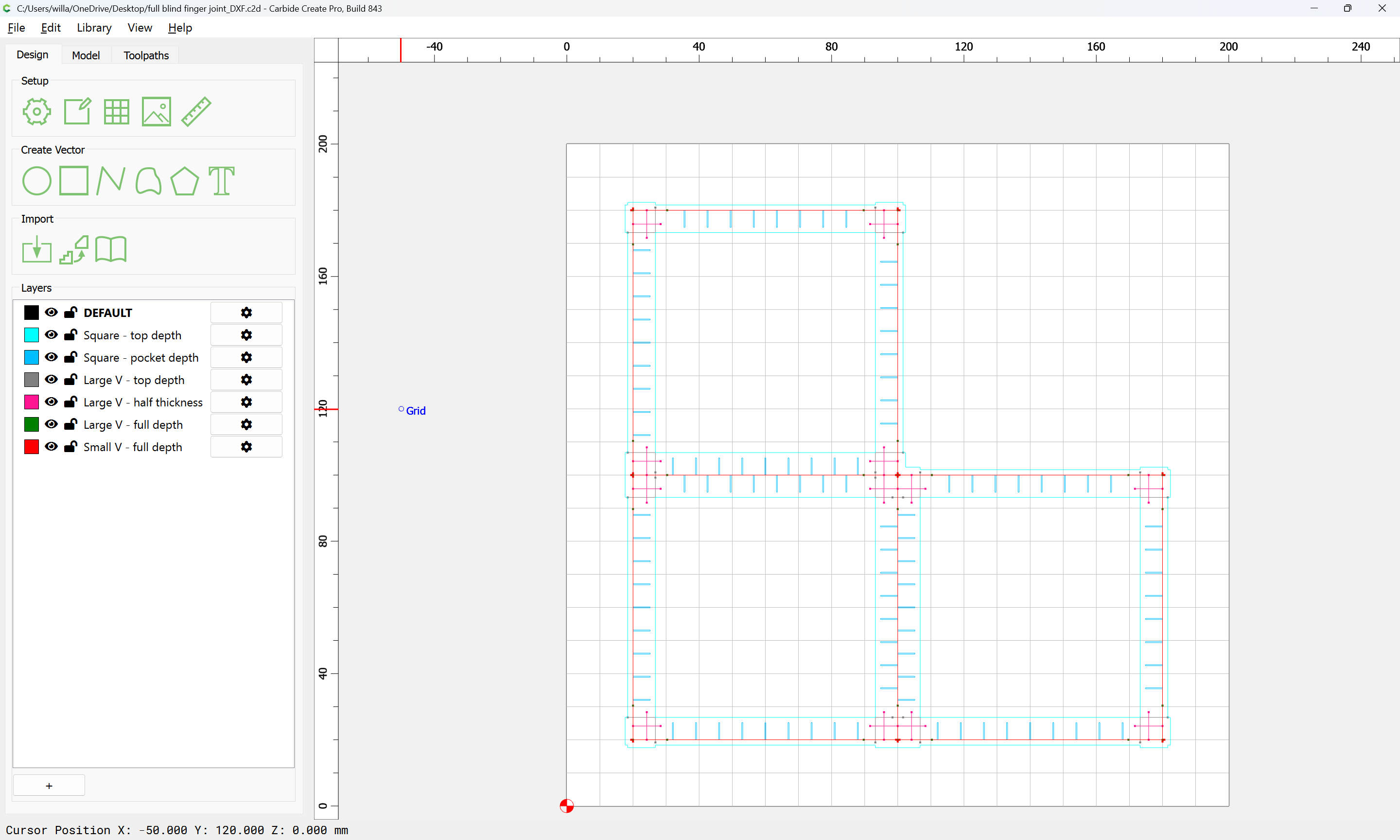
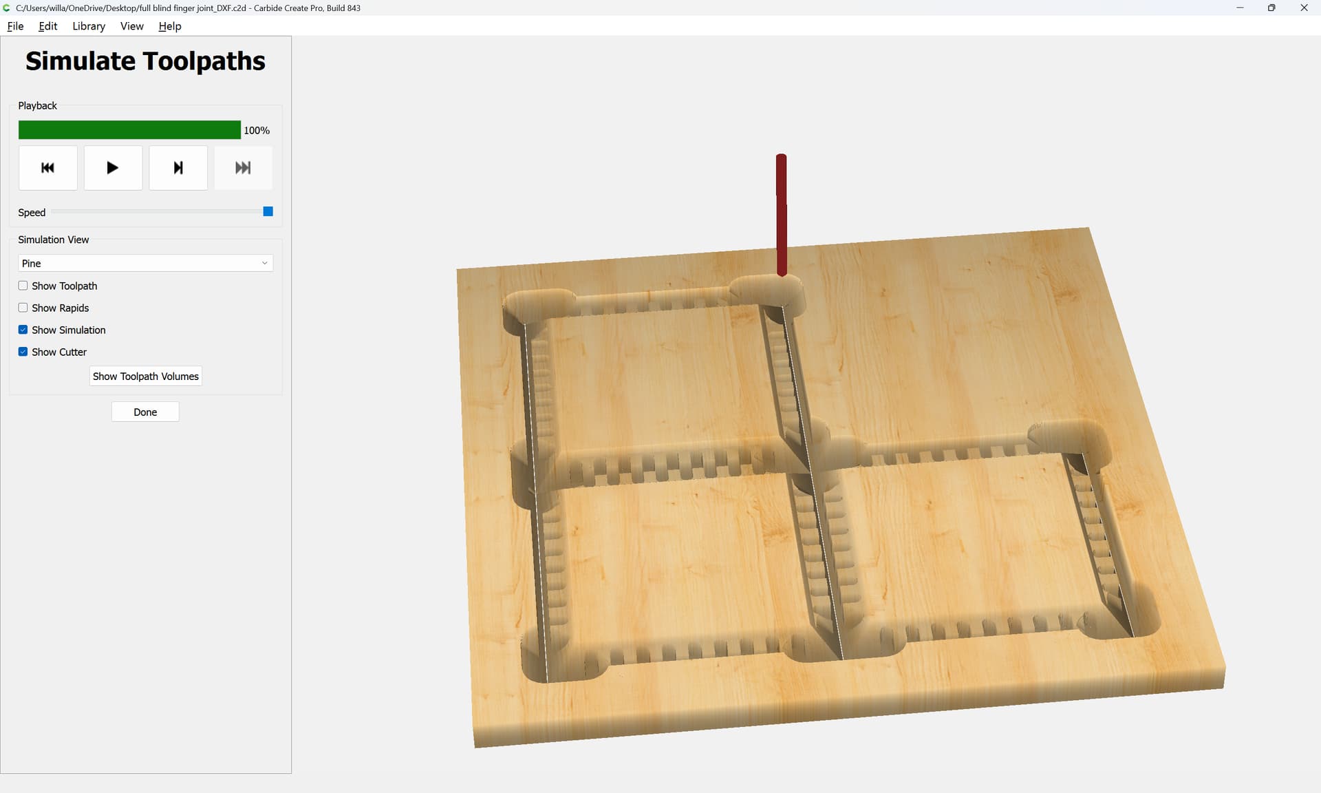
matches up with toolpaths so that the joinery/parts may be cut:
You’ll just need a large 90 degree V tool, a narrow V tool (I usually use a 1/8" 90 degree Kyocera), and a matching small square tool (a #102 will be fine).
4 Likes
I scrolled back and I’m not sure which post you are reffering too.
That specific post was:
and as noted, the box was written up at:
Not sure why the link isn’t working:
https://www.blockscad3d.com/community/projects/1270618
but I put it on CutRocket:
https://cutrocket.com/p/622970cdb482a
and wrote about it at:
(which has a different BlockSCAD link which also isn’t working)
All of the above was in the way of an apprenticeship in learning and working through the pros and cons of various approaches and limitations of older versions of Carbide Create.
Unless there is an objection, I will pull out the posts asking after box-making techniques and put together a master-class on box-making.
As noted, it should all come down to a set of parameters/characteristics:
- overall box dimensions
- stock thickness (after all machining — one option might be to machine down the inner surfaces)
- box features, e.g., type of lid, possibly hardware
and will require a specific set of endmills:
- a large 90 degree V tool able to cut a bit more than half-way through the final part thickness
- a narrow square tool for cutting the interior box joints and the narrow channel in-between the parts
- a narrow 90 degree V tool either the same diameter, or slightly greater than the diameter of the narrow square tool (a pair of 3mm square and 3.175mm has worked well)
Folks should feel free to post here about the boxes which they wish to make as well as the features which they want and I’ll work up instructions/files to suit.
1 Like
By way of background, some of the limitations which were being worked through were:
- OpenSCAD only being able to describe closed regions
- said closed regions needing to be separated by location for want of any other option
Since then, three things have happened:
-
Carbide Create has gained a facility for associating a toolpath with the contents of a layer, allowing one to make template .c2d files
-
DXF import in Carbide Create was markedly improved:
Build 839
New
All-new DXF parser that handles less-popular parts of the DXF format better.
including importing the layer associations.
- in my own project using Open(Python)SCAD, I have worked up a mechanism for describing tool motion and writing out DXF files which may be unclosed:
including colour-coding and assigning to layers.
So, if someone will let me know:
- what dimensions they wish to use when making a box
- what features the want for it to have (e.g., lid treatment)
- what stock/part thickness
I’ll gladly work up a files for making same.
Hi Will,
I would love to take you up on your offer. I want to make a keepsake box for my wife for an anniversary gift. I’d like the box to be 12 x 8 x 6 (WxLxH) inches and made from walnut + maple (majority would be walnut with maple accents). I was thinking something in the 1/2" -3/4" thickness. I like to have unique joinery. You and I talked once about the issues with dovetails and the Shapeoko, but you said that there are other cool joinery that could be done instead. I’d love to explore other options with joinery and not just have a “box.”
Can you help me with the project, please (… and help me give my wife a super cool anniversary present)?
Thank you!
Sincerely,
Roy
My predilection is to not show endgrain — as I’ve noted in other discussions here, a fine cabinetmaker who taught me a great deal when I was growing up inculcated in me the opinion, “Endgrain is like a person’s belly button, you know everyone has one, but for the most part, you don’t want to see it, unless it’s someone special.” If I want exposed joinery, well, that’s why I have a collection of dovetail saws:
and we did cover making dovetails here before:
and various other joinery options, e.g., Knapp joints:
There is also already specialty software for this sort of thing (for those folks who have machines/workholding setups for them):
https://g-forcecnc.com/jointcam.html
https://fabrikisto.com/tailmaker-software/
That said, I find a continuous grain/seamless box with no end-grain showing (once of these days I’m going to get a nice bandsaw which will allow re-sawing) far more interesting in most cases:
One additional possibility would be to then modify the box by cutting in grooves and adding splines, but mostly that ends up looking like lipstick on a hog.
So, this evening, I will walk through making a:
- 12" x 8" x 6" (W x L x H) box
- from thicker stock, possibly up to 1/2" — one concern about this technique is it is limited in stock thickness by the size of the tooling selected, another is that wood thickness needs to be proportional to the size of the project, and one doesn’t want a heavy/clunky project (which looks as is if it was made out of lumber pulled off a shelf w/o further thought or processing)
However, you did not specify lid — there are 3 which are pretty easily done:
- sliding
https://cutrocket.com/p/622970cdb482a
- integrally hinged
https://cutrocket.com/p/67b86d0d17056
- externally hinged with hardware (after being cut apart)
just let me know your preference on that and we’ll work through this this evening with my joinery technique — if you still want exposed endgrain you can then either modify the box after making it, or apply what is learned here to implement your own style of joinery.
1 Like
Just to cover all bases, there is one further notable box option — sculpting a top/bottom and up to 4 sides out of a single piece of material.
This is done to good effect in:
https://cutrocket.com/p/5d4b92b17fbcc
and for a clever variation, see:
Thank you for the files and explanation Will. I’m going to give this a whirl. Thanks again!
Thank you, Will! For the lid, I just purchased a “JointMaker Pro,” so let’s go down that route if that’s ok.
1 Like
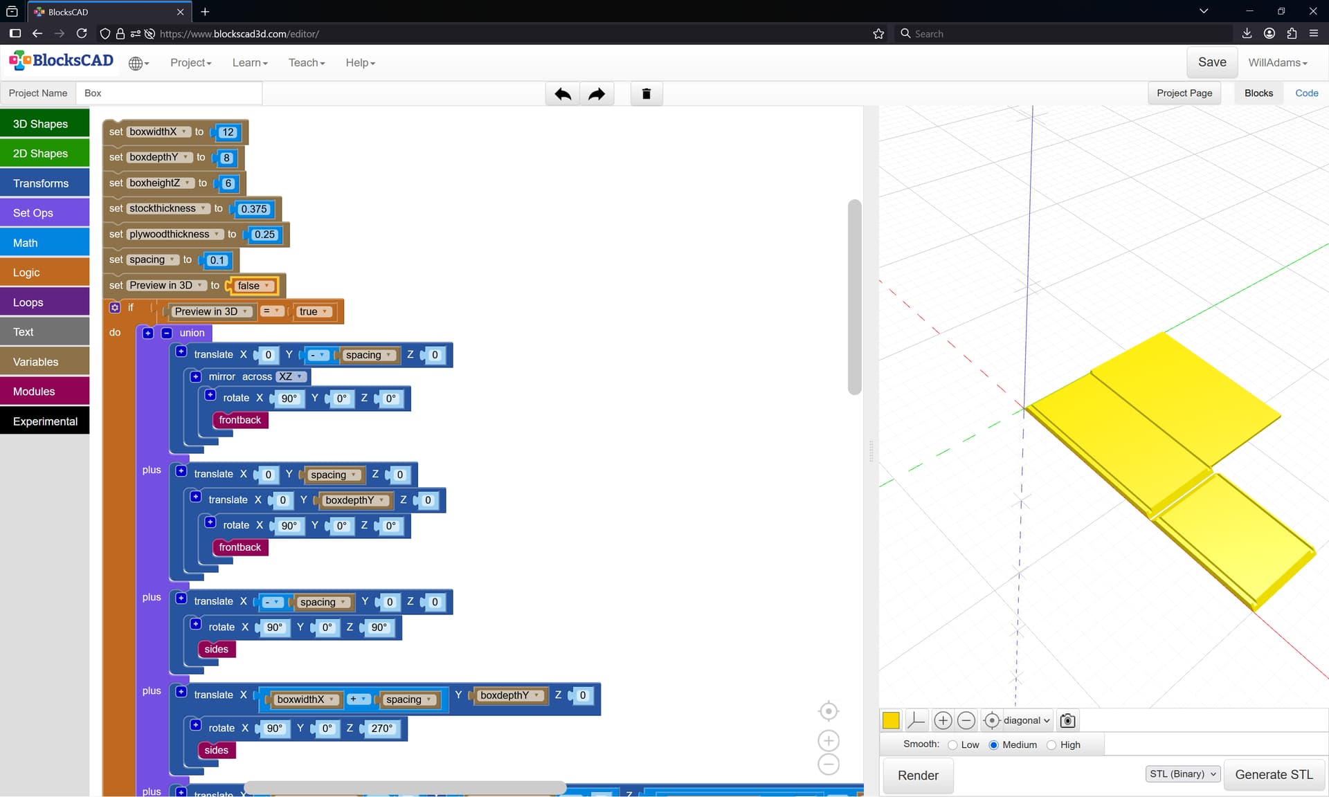
To work through the proportions initially we make a BlockSCAD file for previewing things:
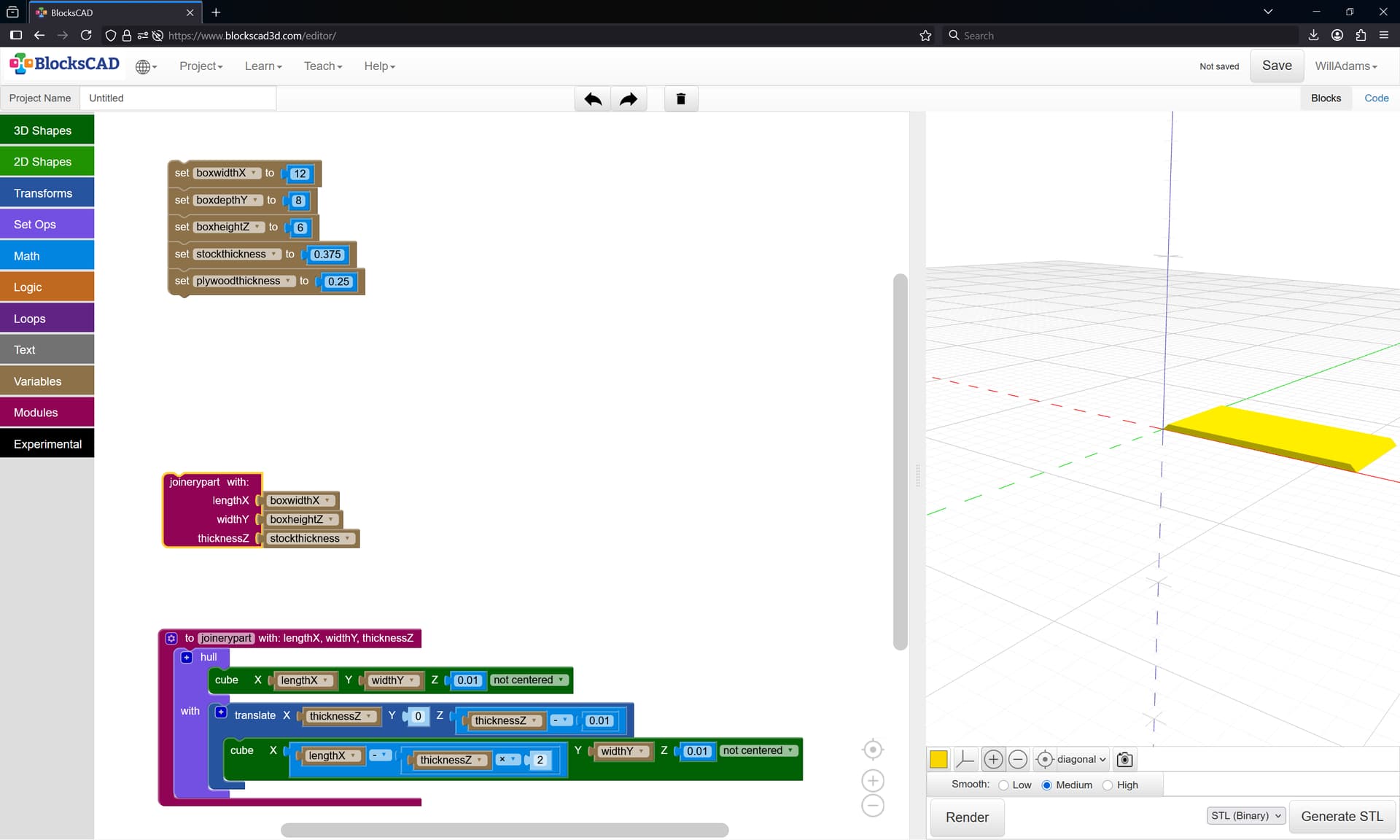
which just wants a bit of rotating and re-arranging:
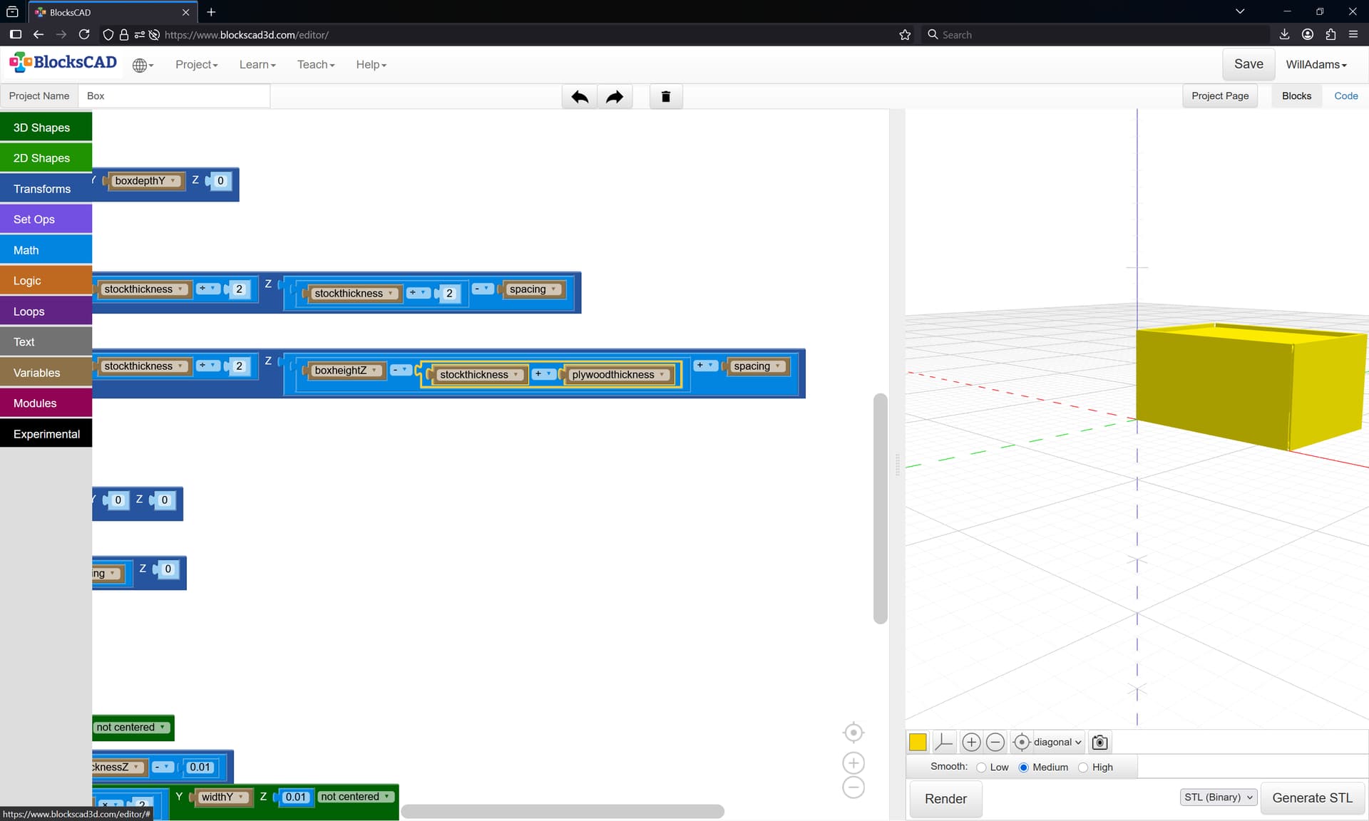
and which we can use to visualize the parts as well:
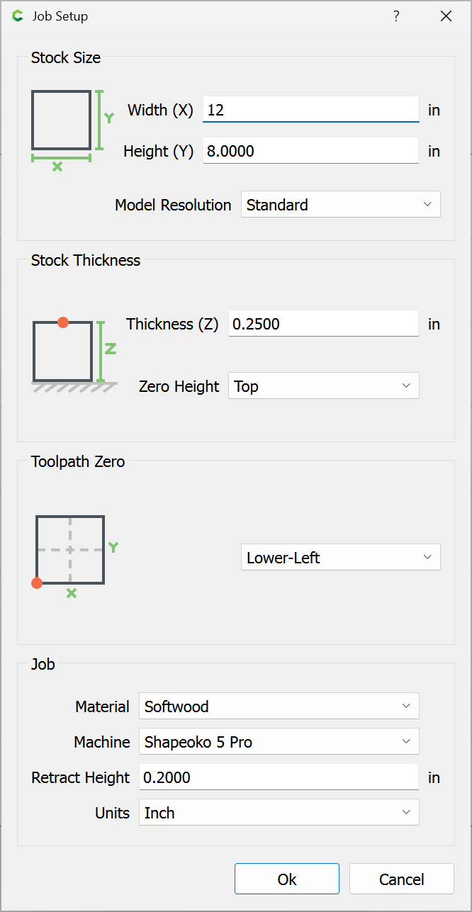
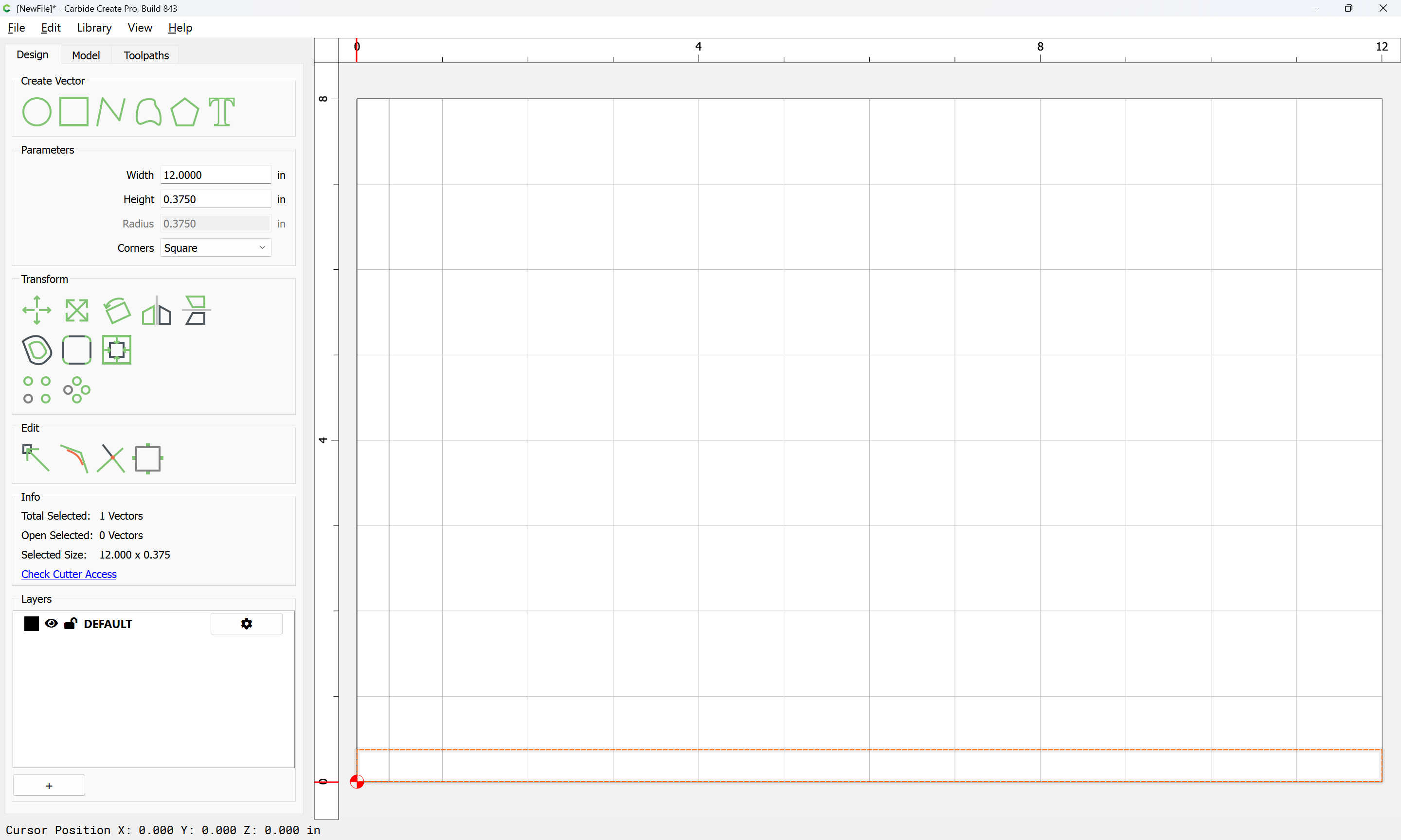
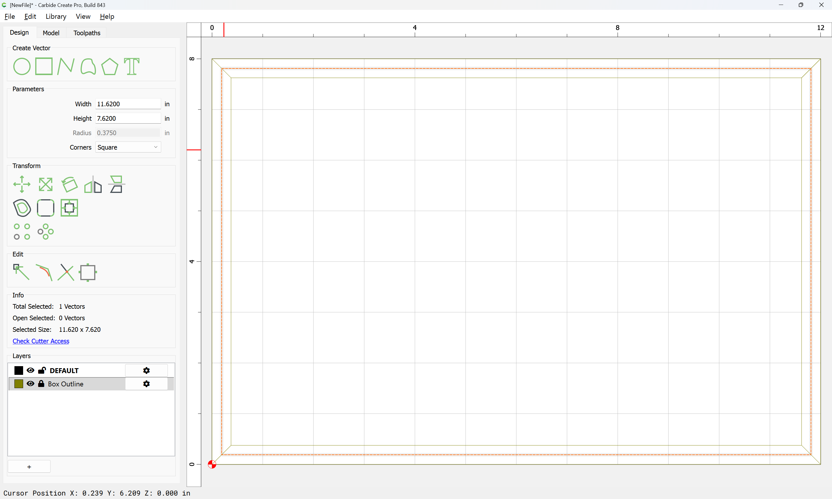
Setting up cutting the front/side in Carbide Create is pretty straight-forward:

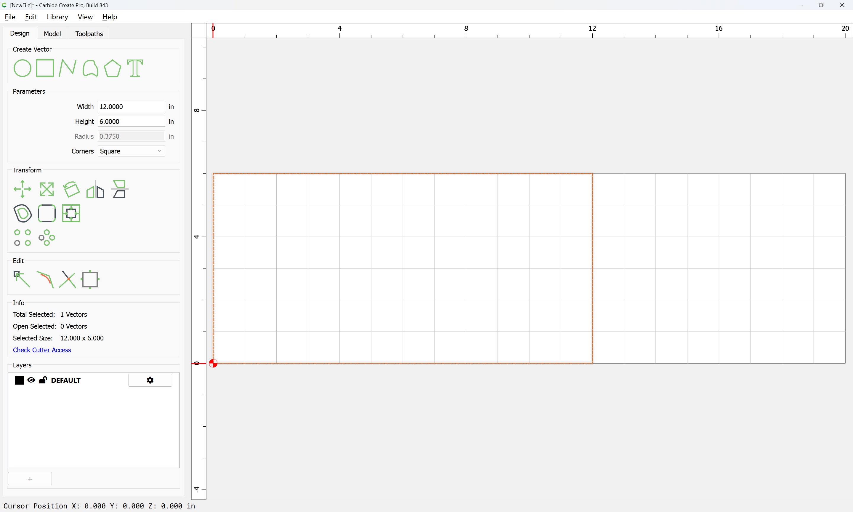
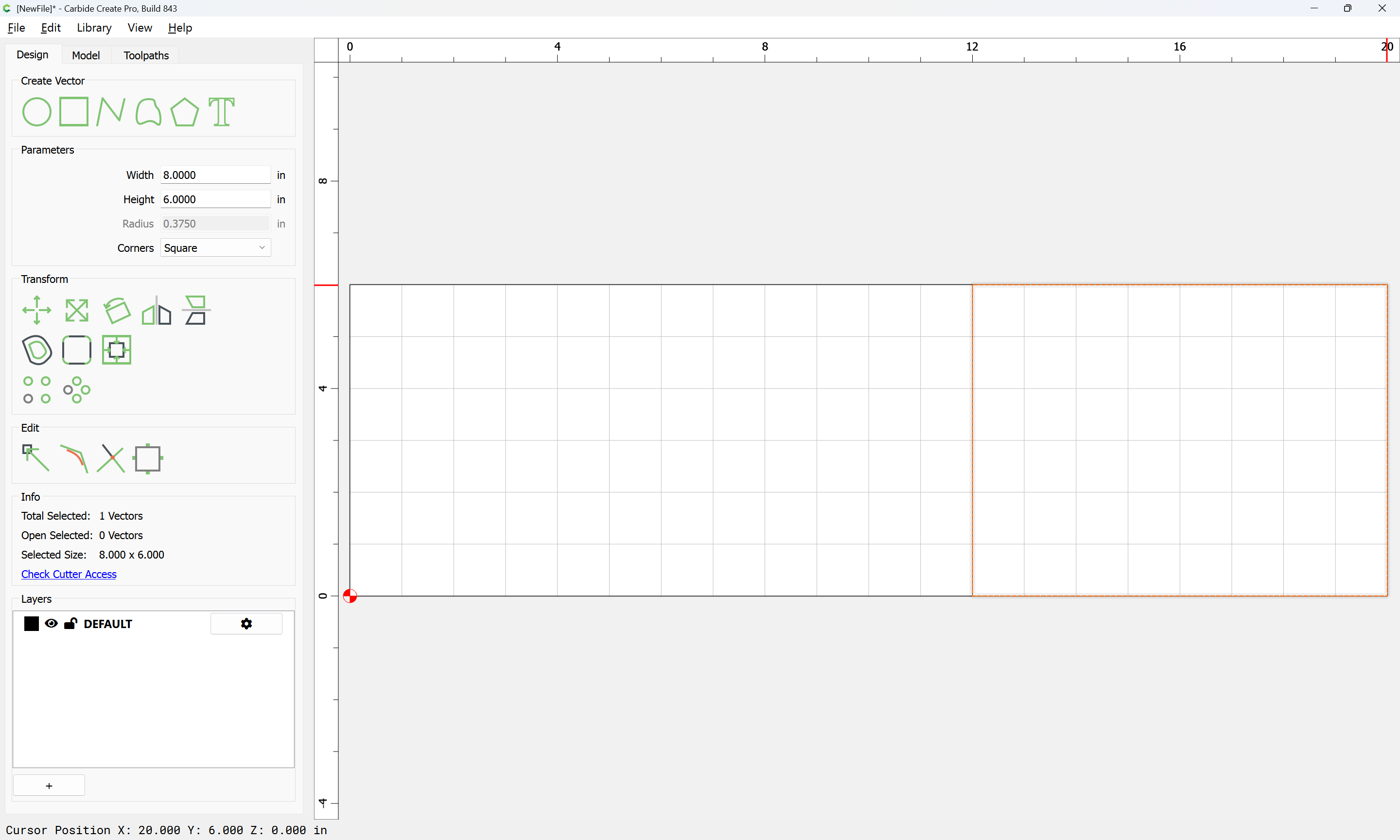
with one consideration being where the cut for separating the lid will need to be — 3/4 of the height for the bottom, and 1/4 for the top seems workable:

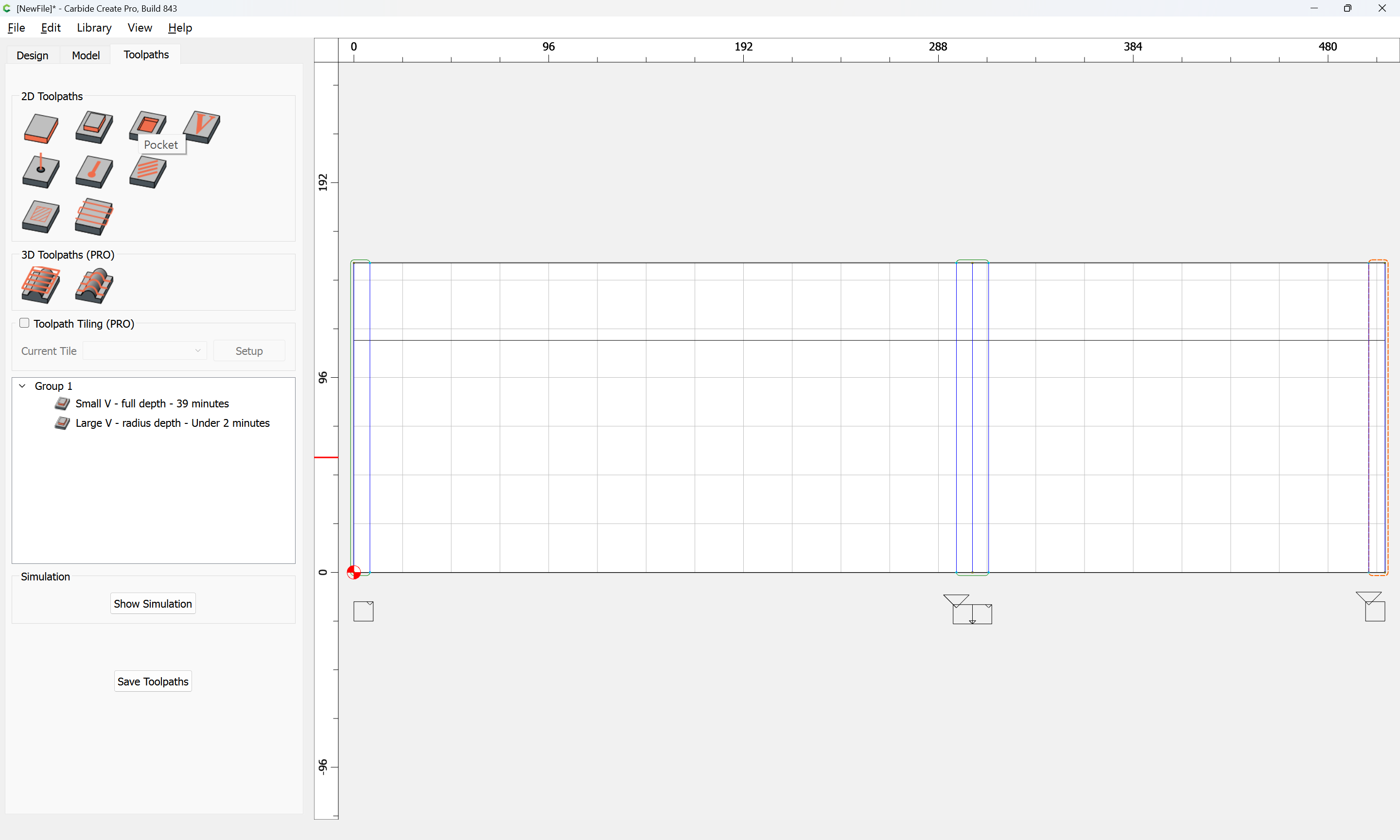
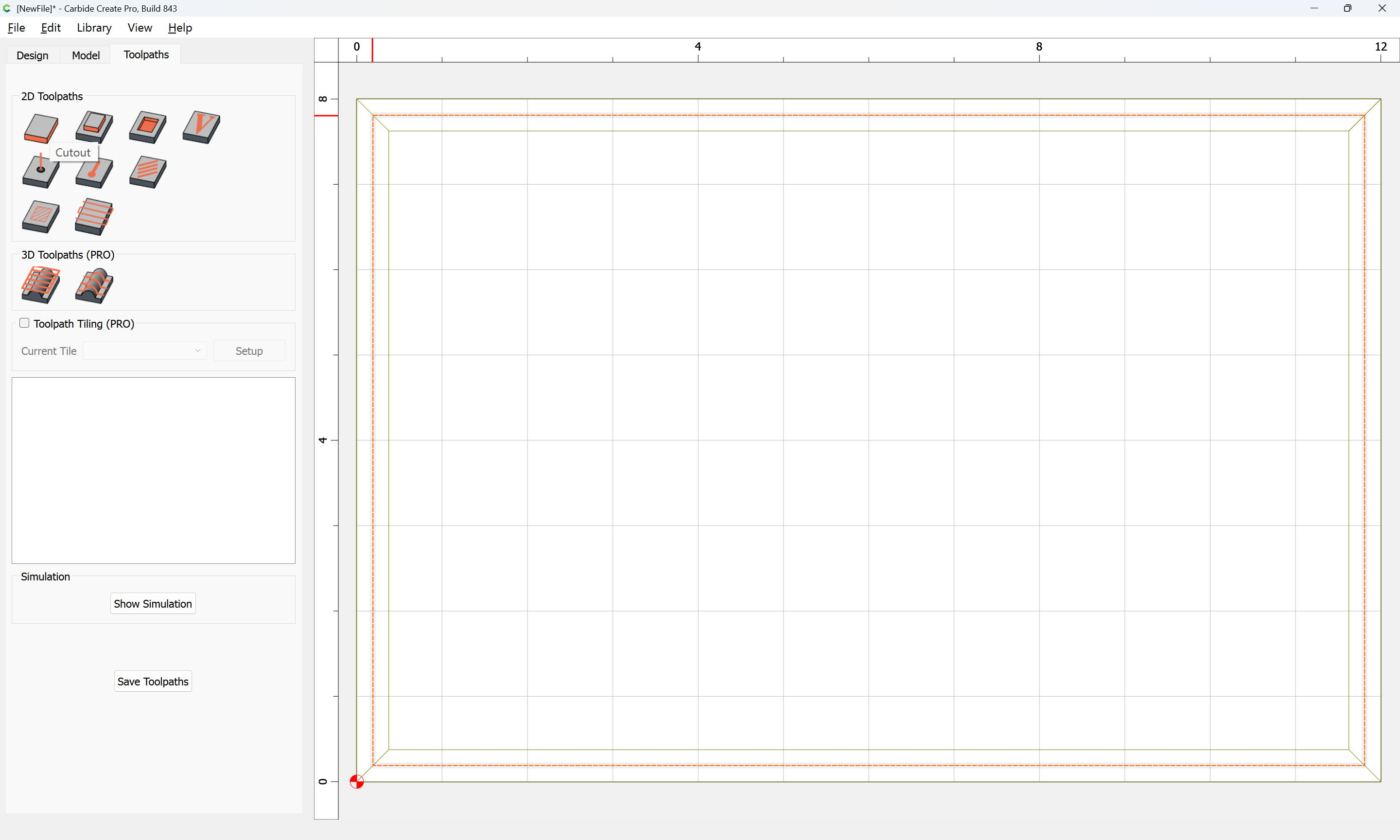
Then it’s simply a matter of setting up the toolpaths…
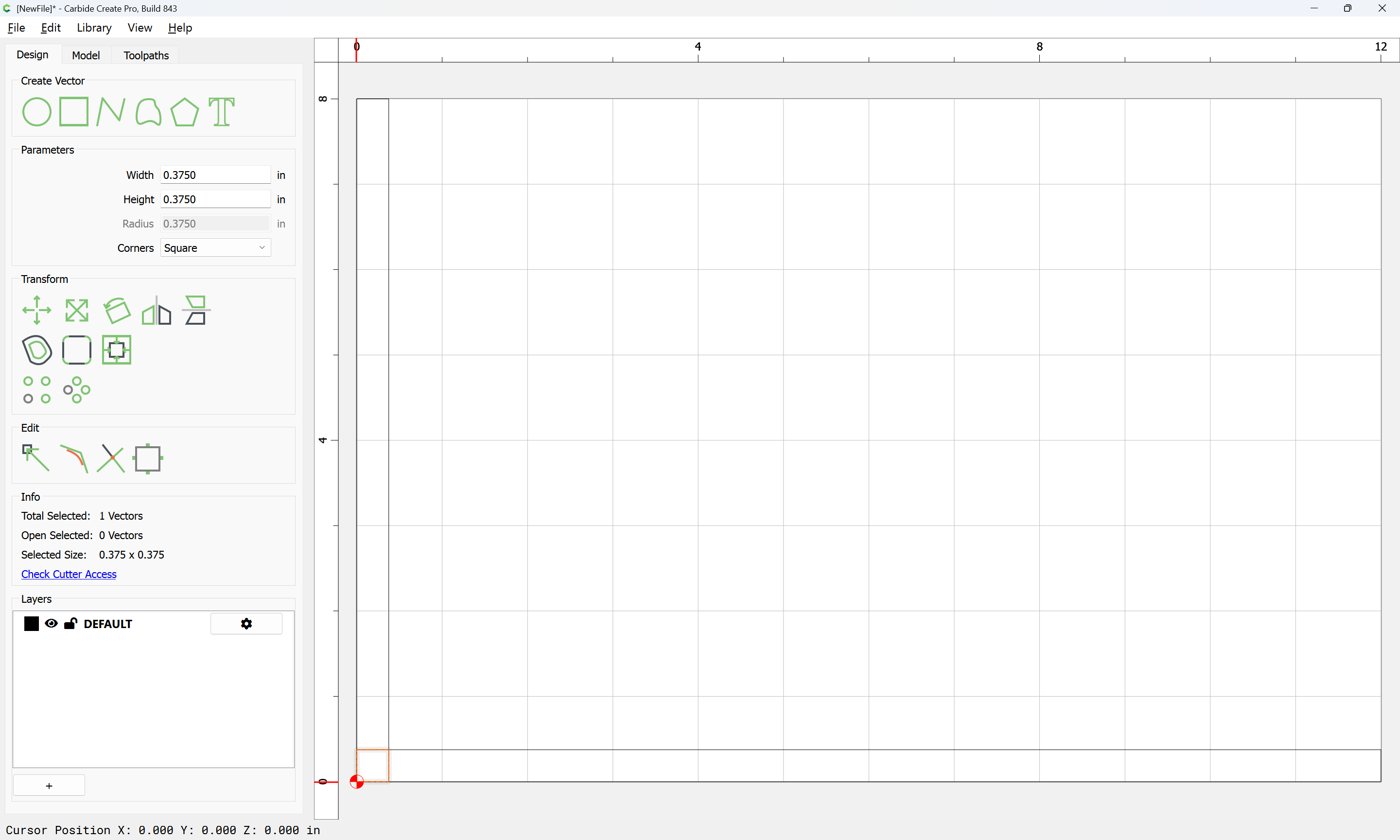
Setting up the toolpaths requires drawing up the stock in profile:
as well as the tooling:
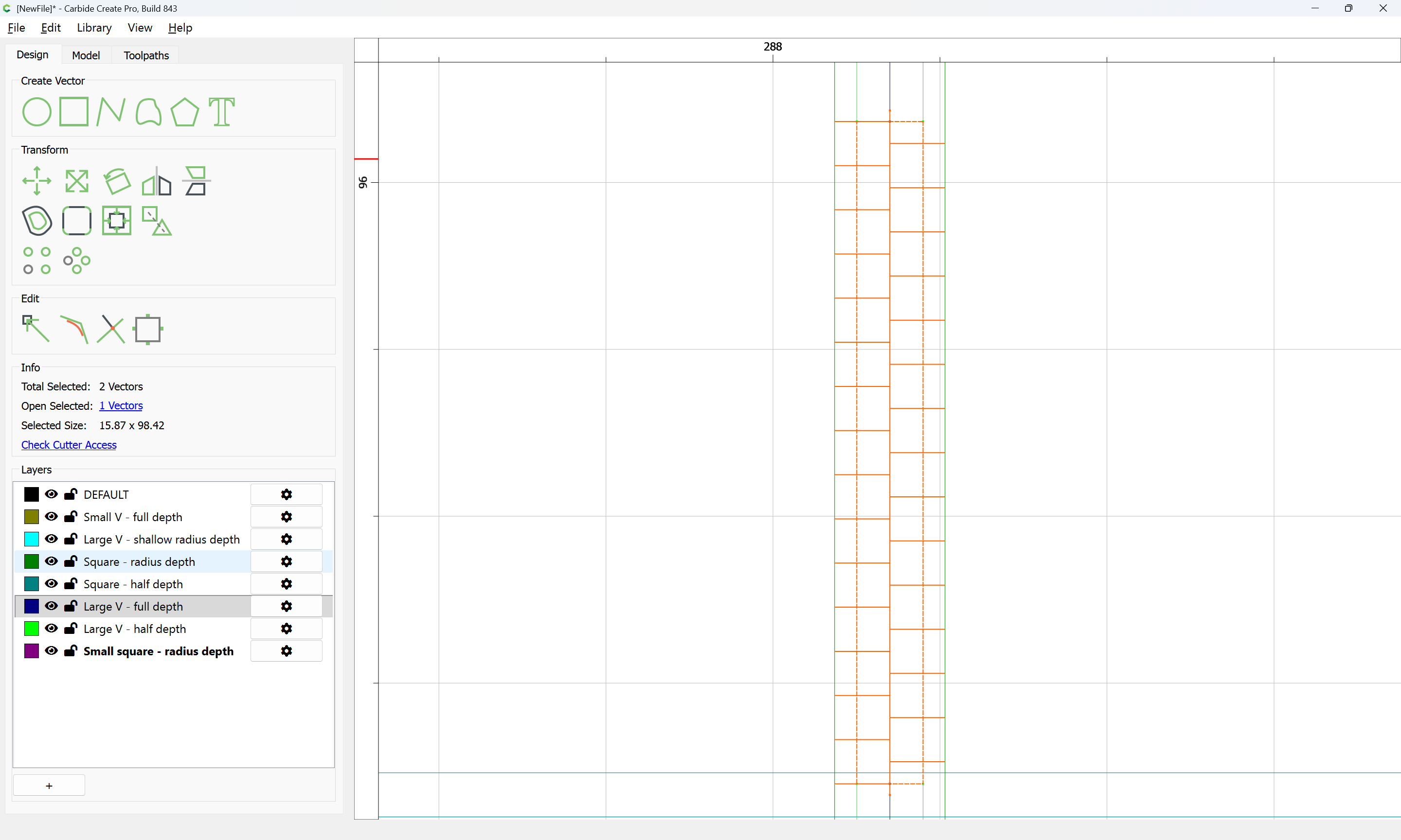
Since a narrow V tool will be used to cut a channel along the edge of the joint, that is positioned first:
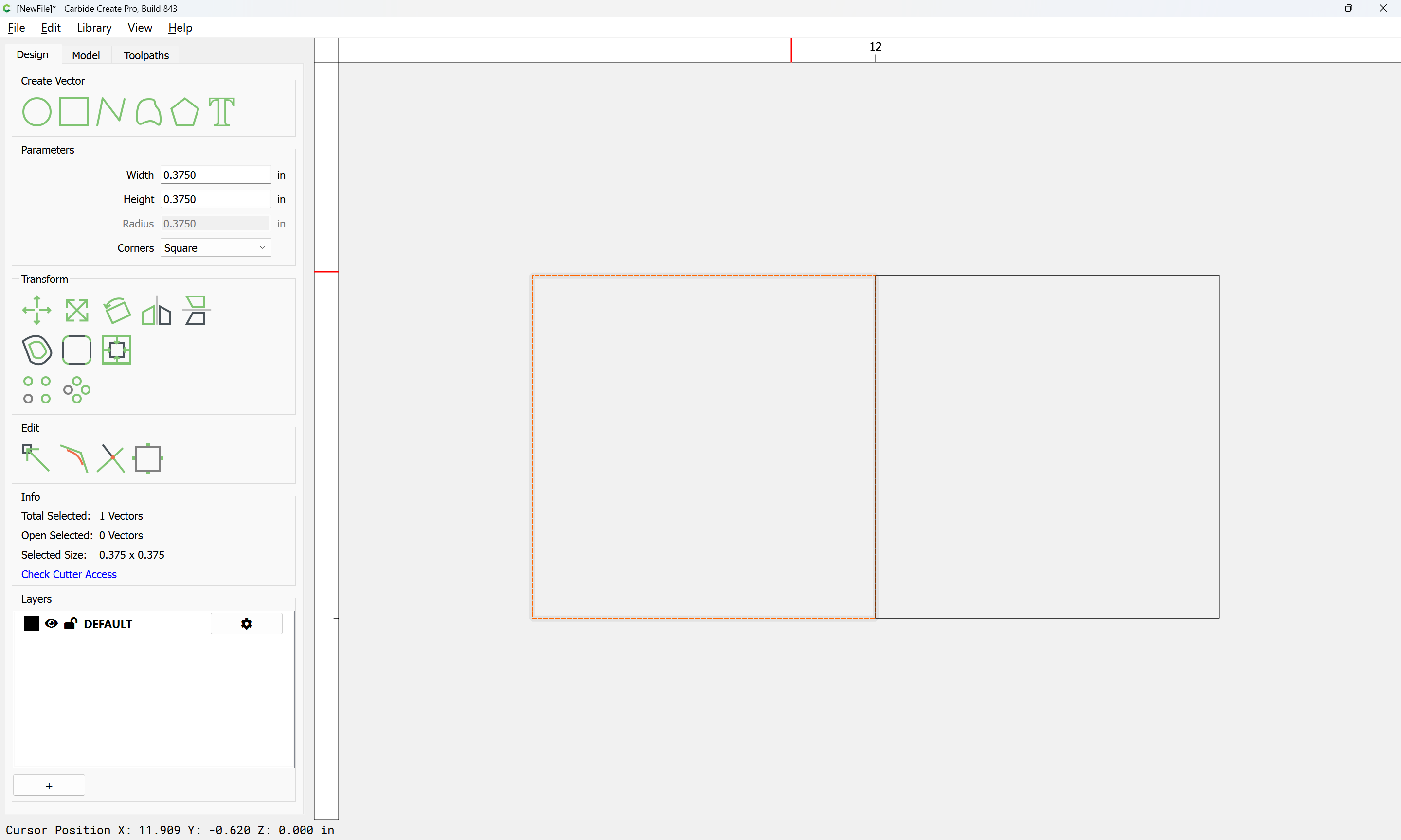
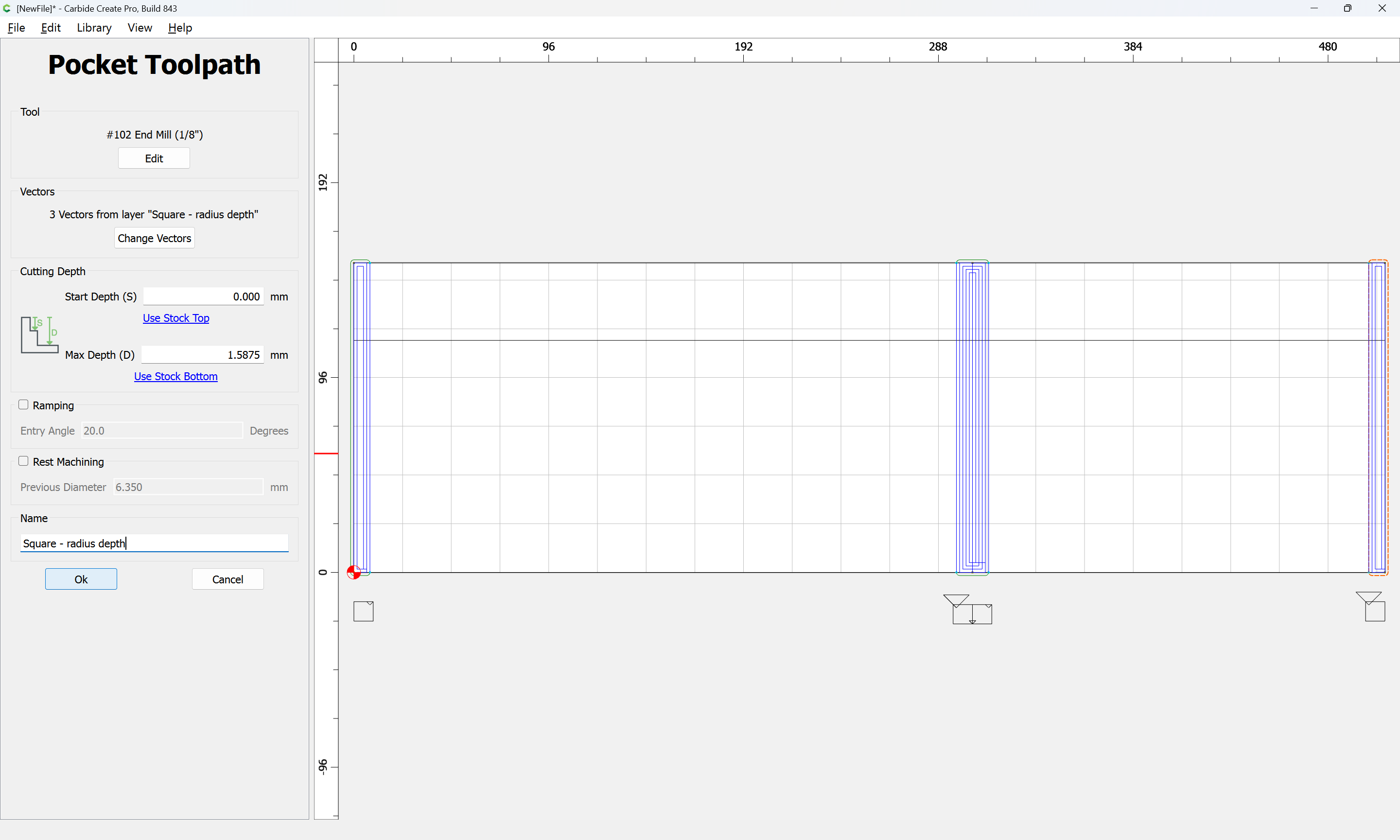
The toolpath for this is simply a line which defines the edge of each joint, for which we make a layer:
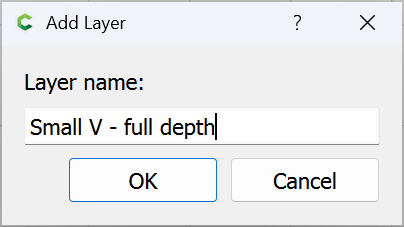
and then draw lines:
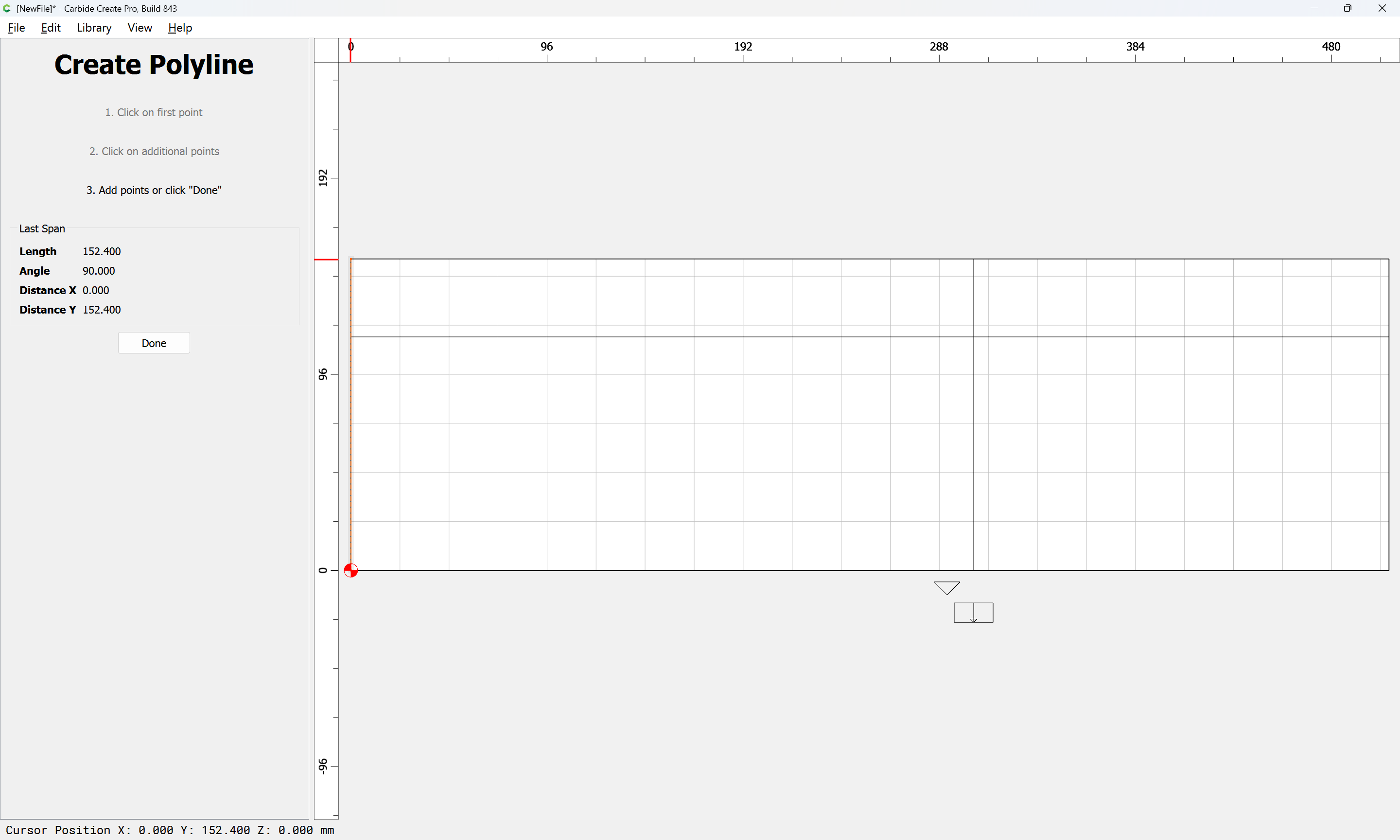
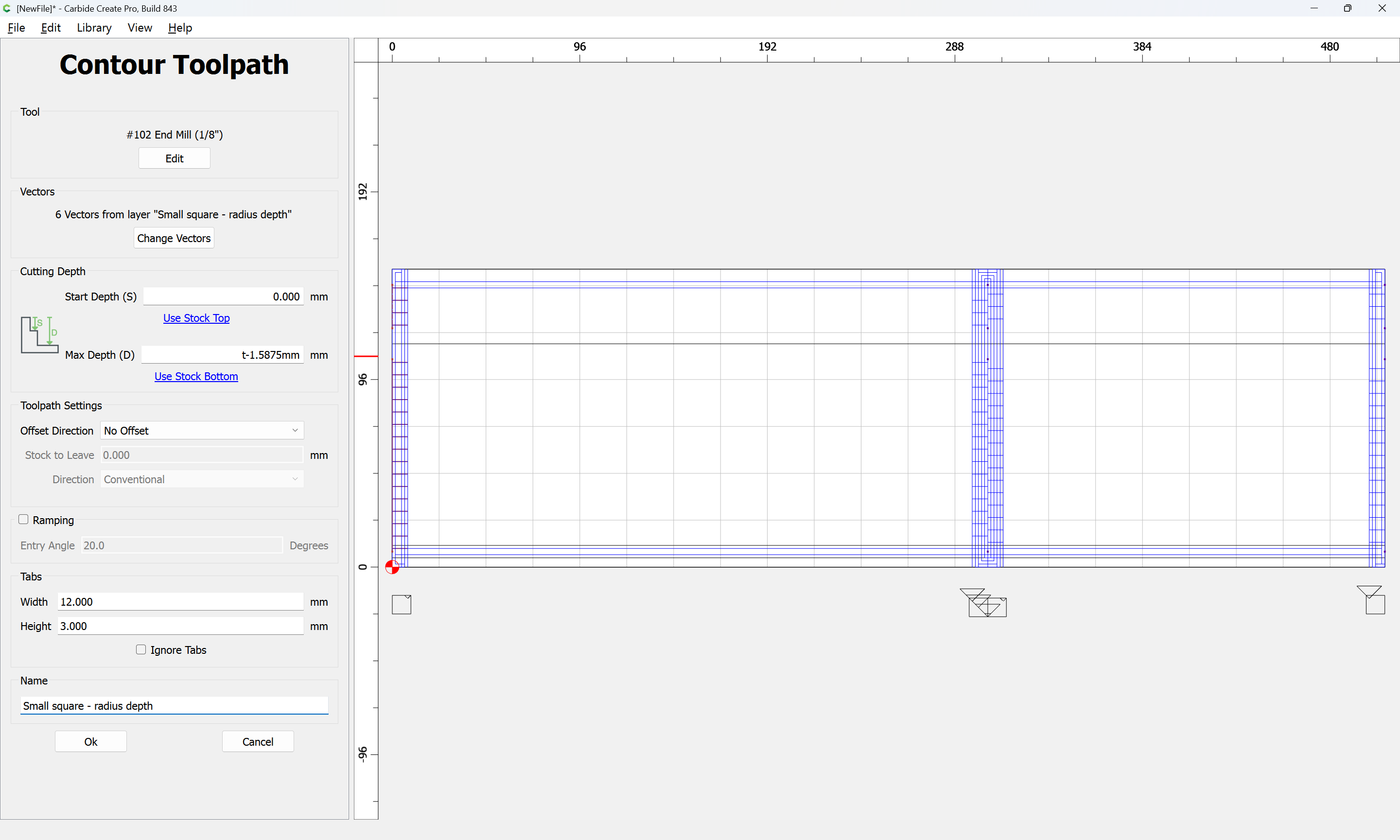
and then assign a toolpath to:
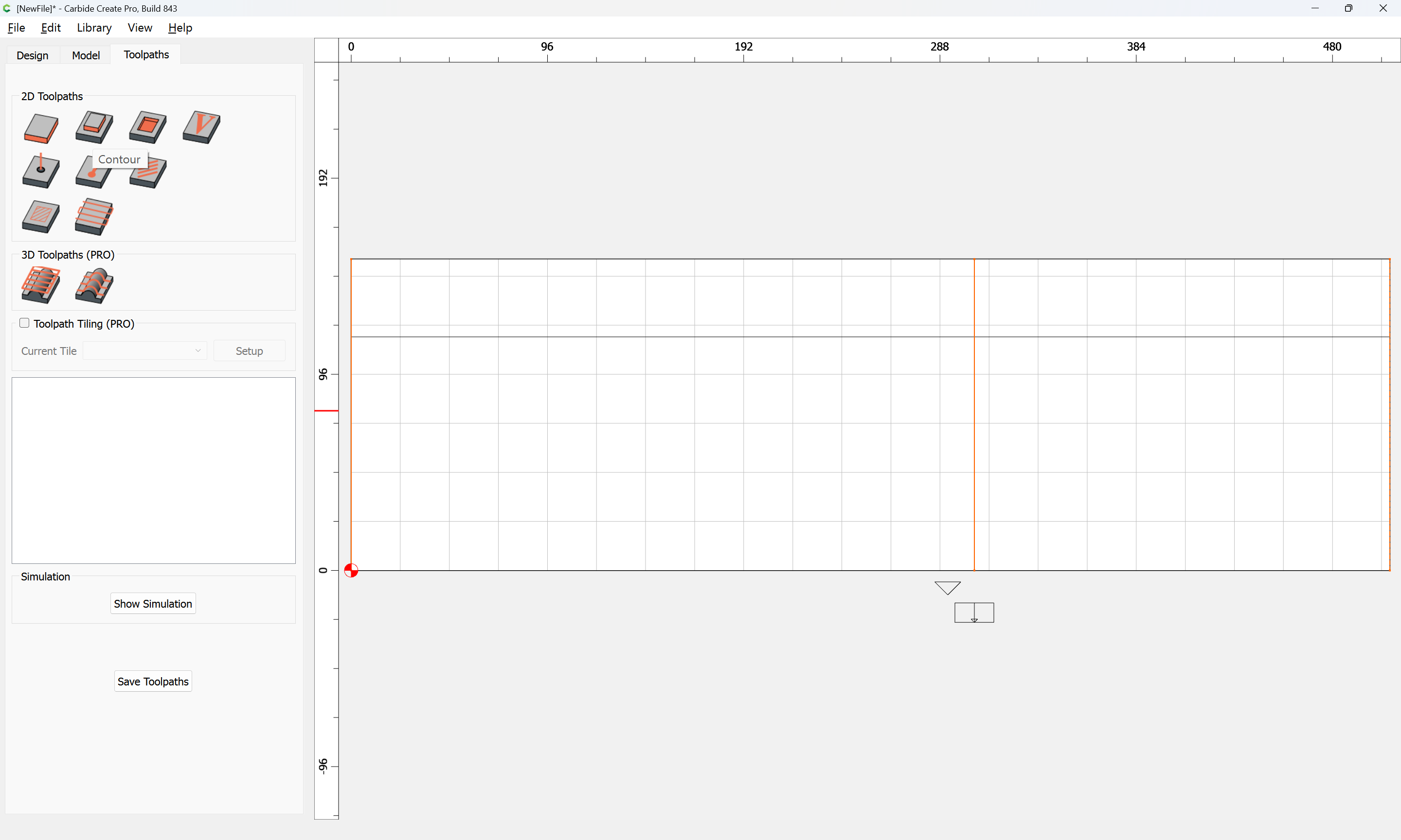
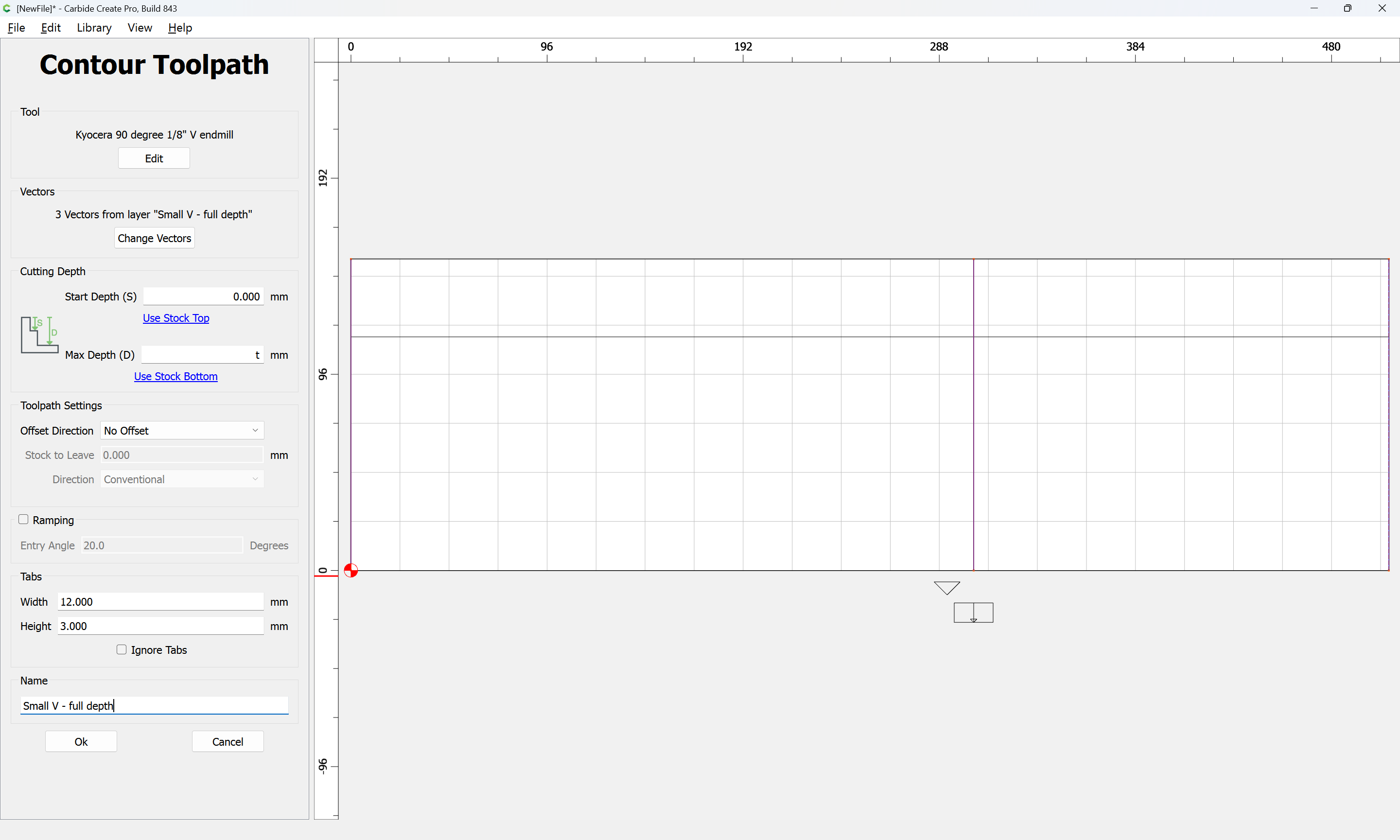
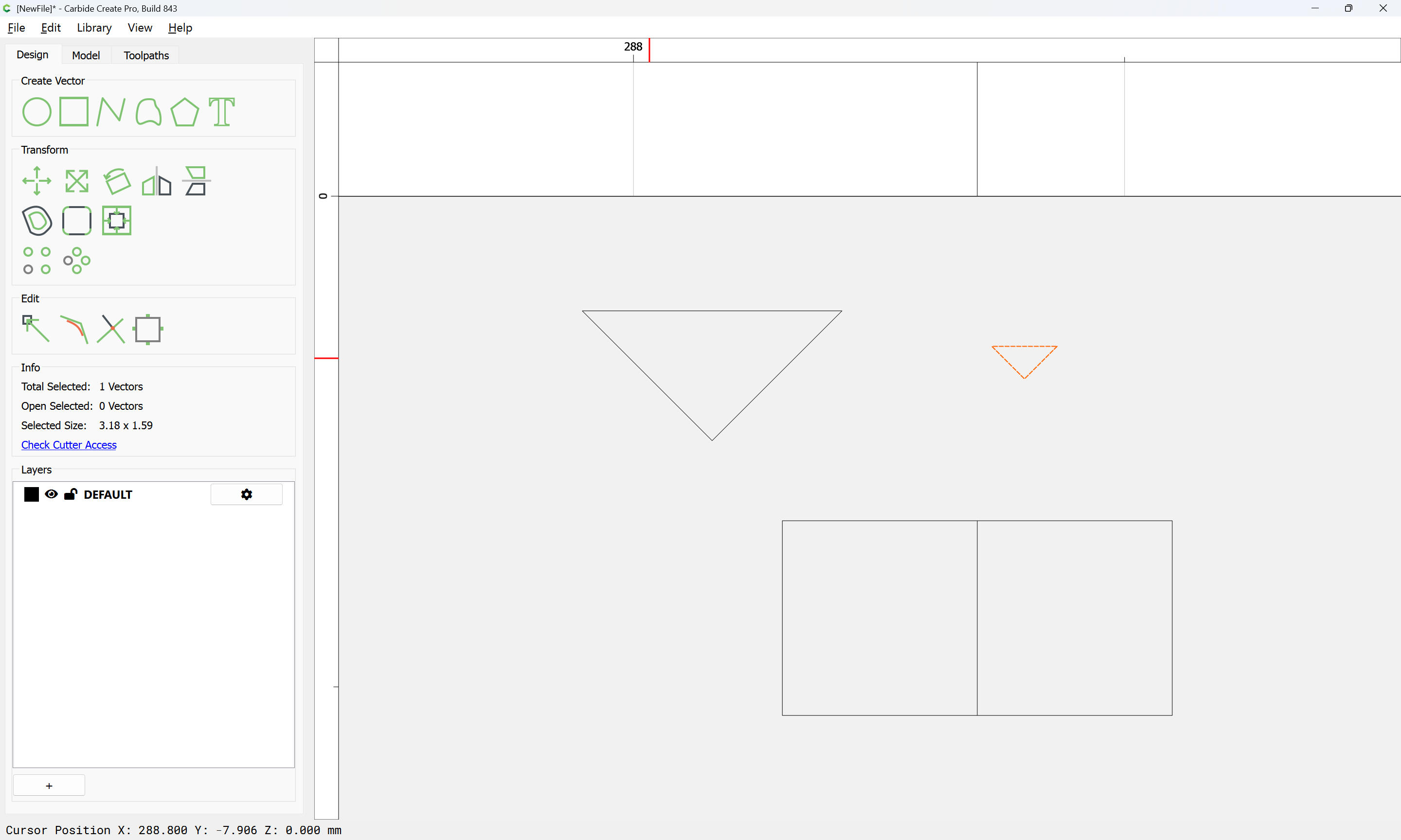
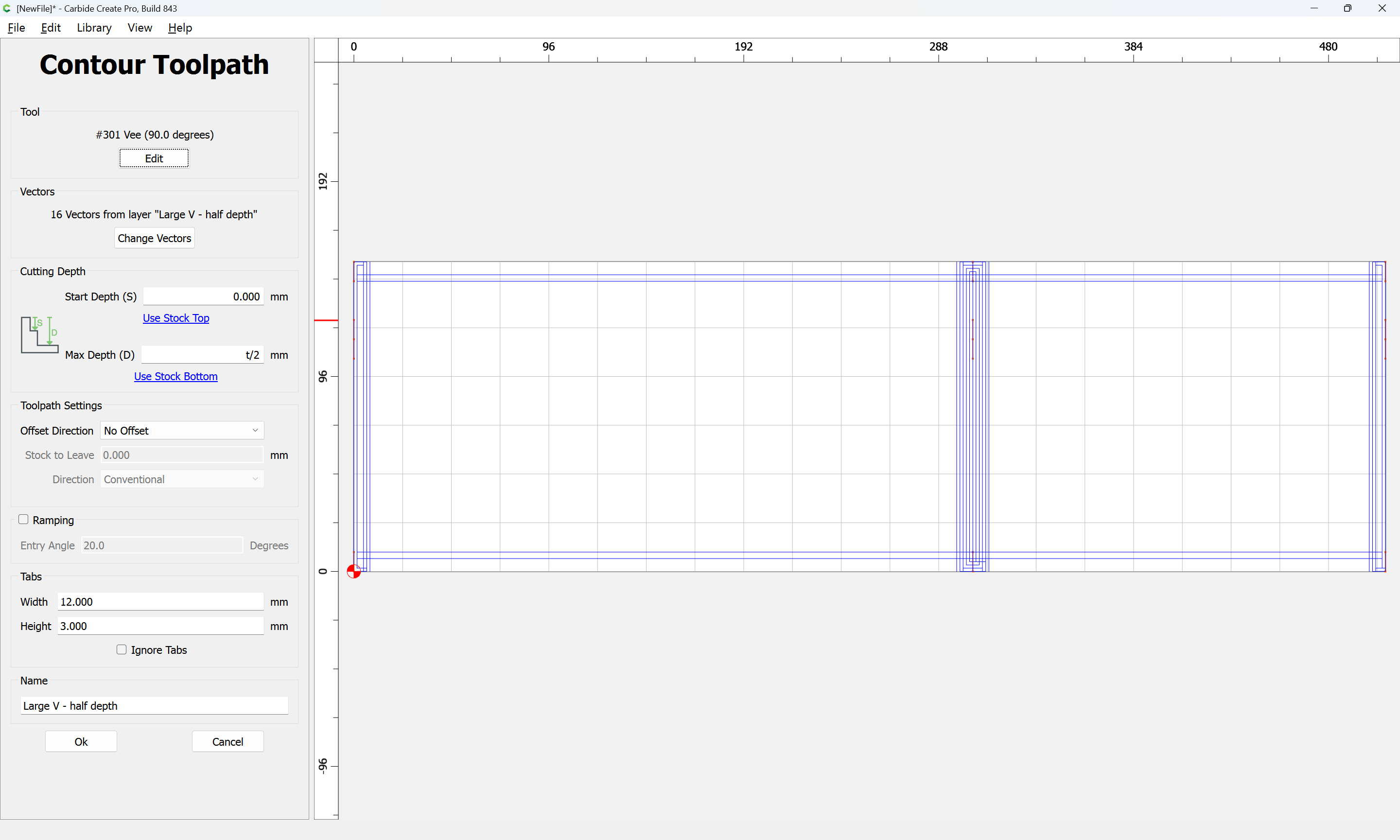
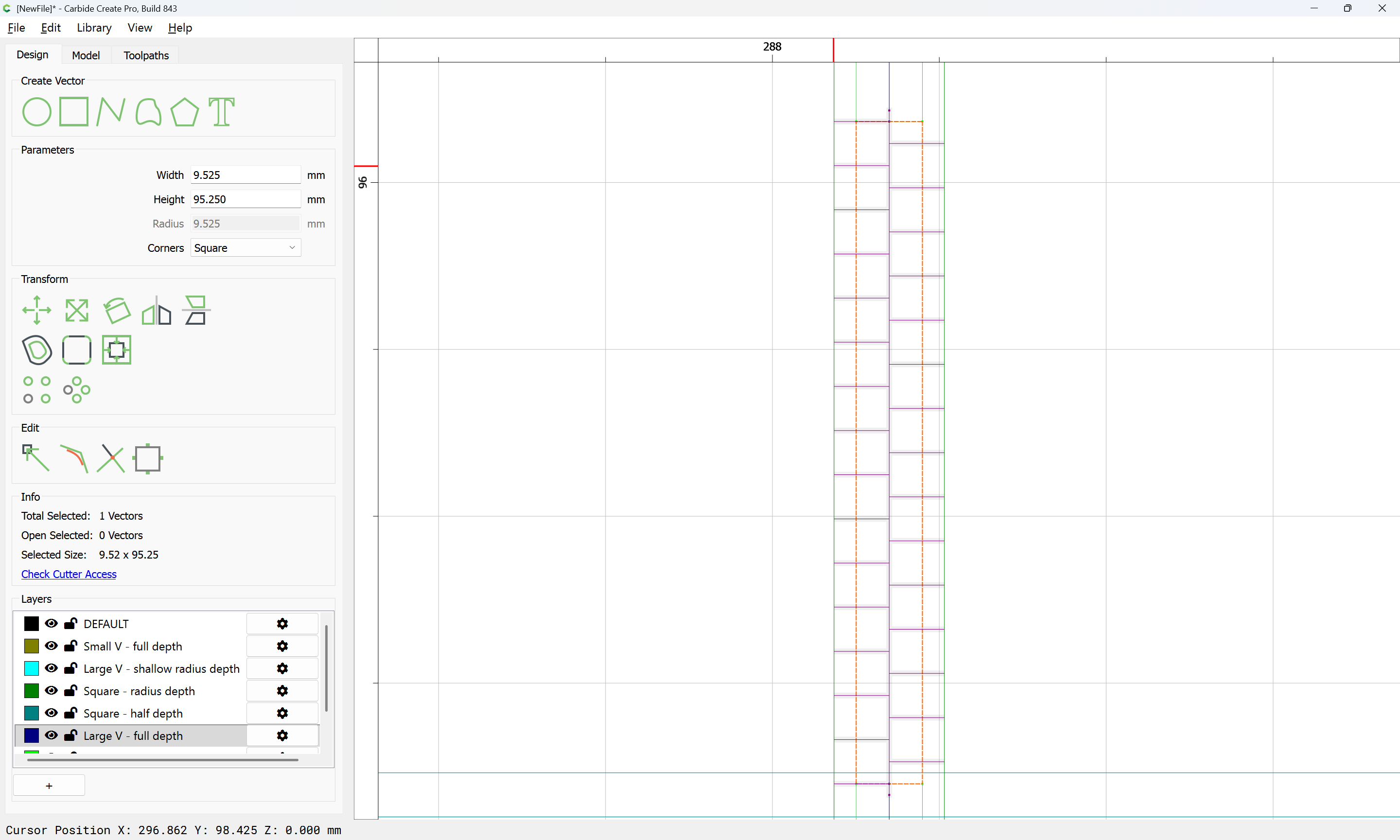
There will need to be a matching cut at the top of the joint:
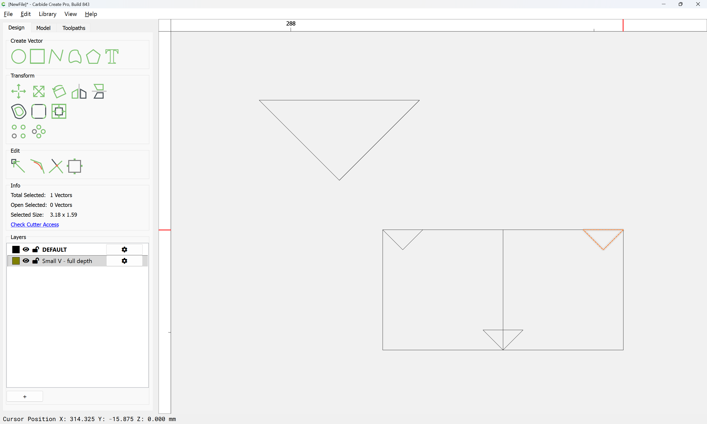
which arguably, is better cut with the Large V tool:
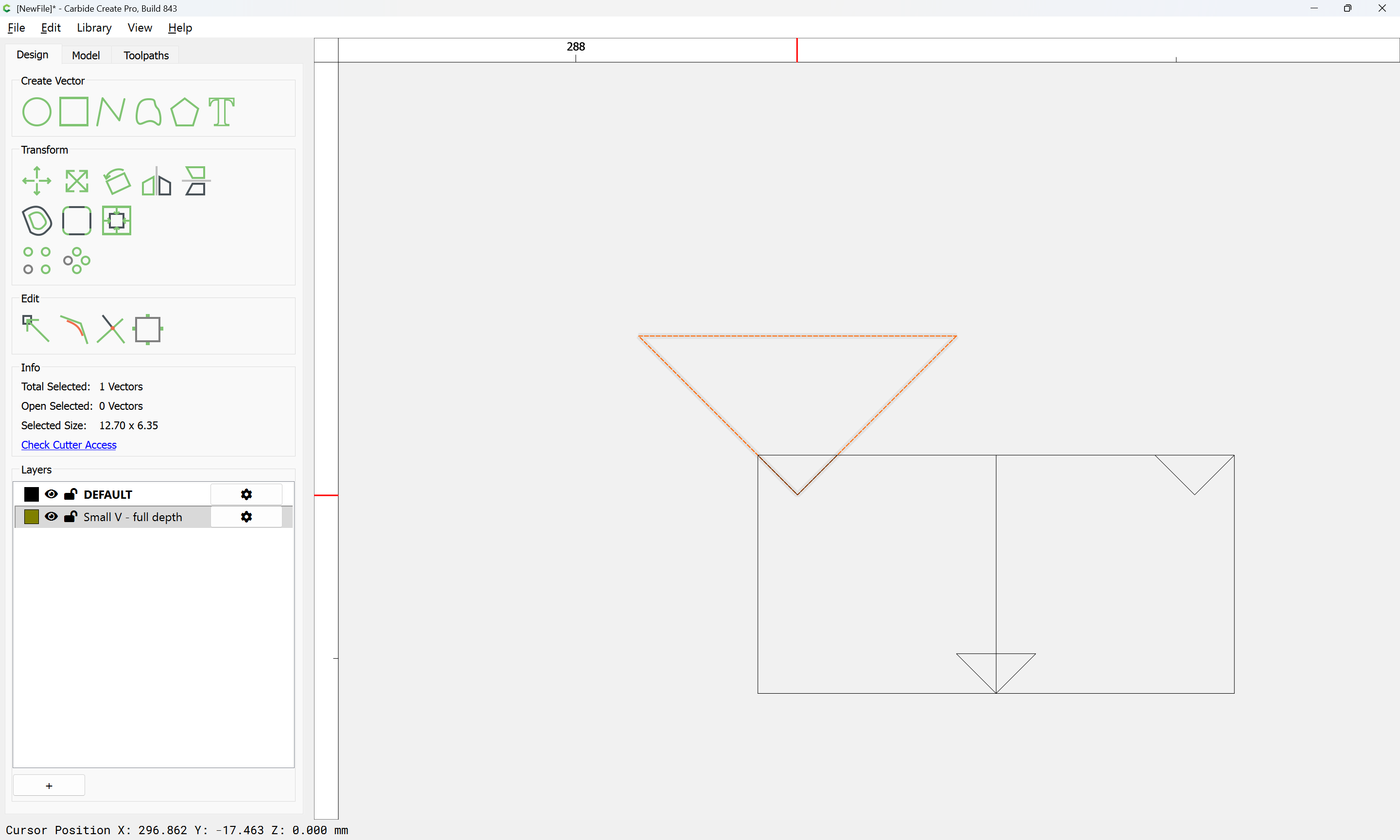
which will want another layer:
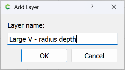
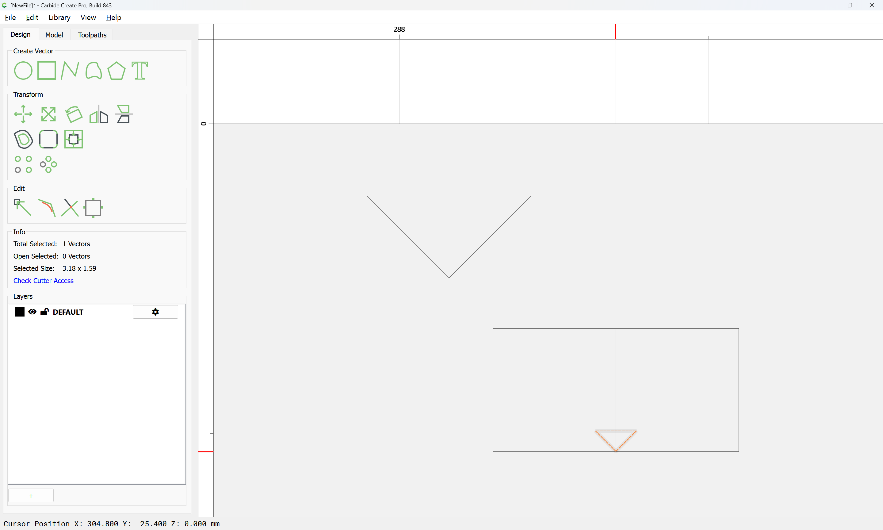
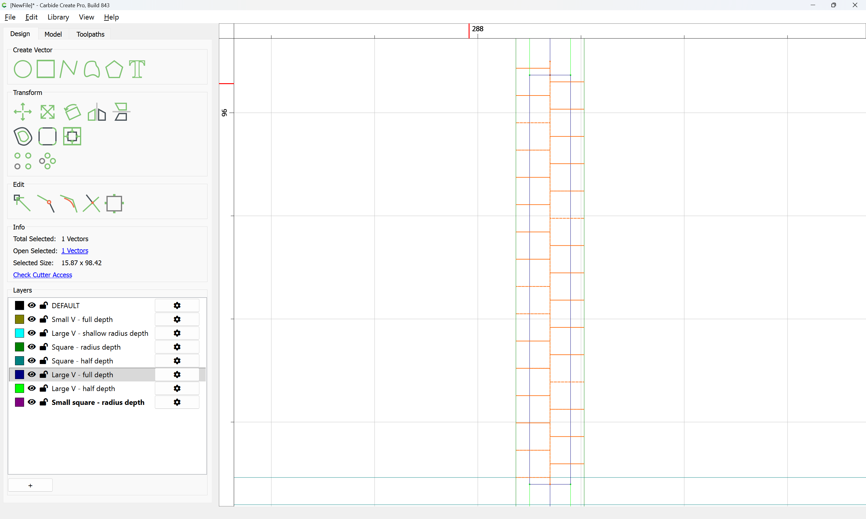
and for which we draw a suitable line and position it:
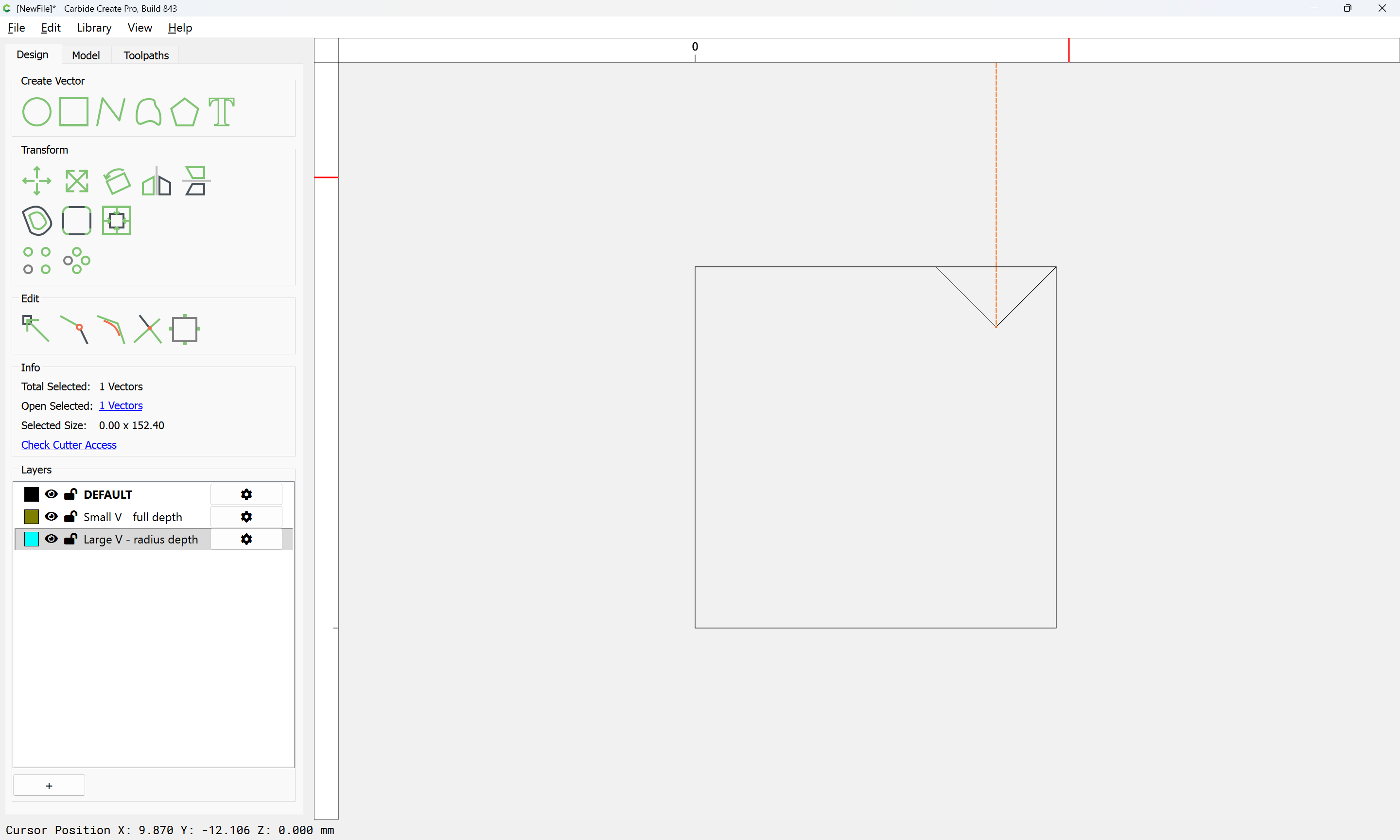
duplicating as need be:
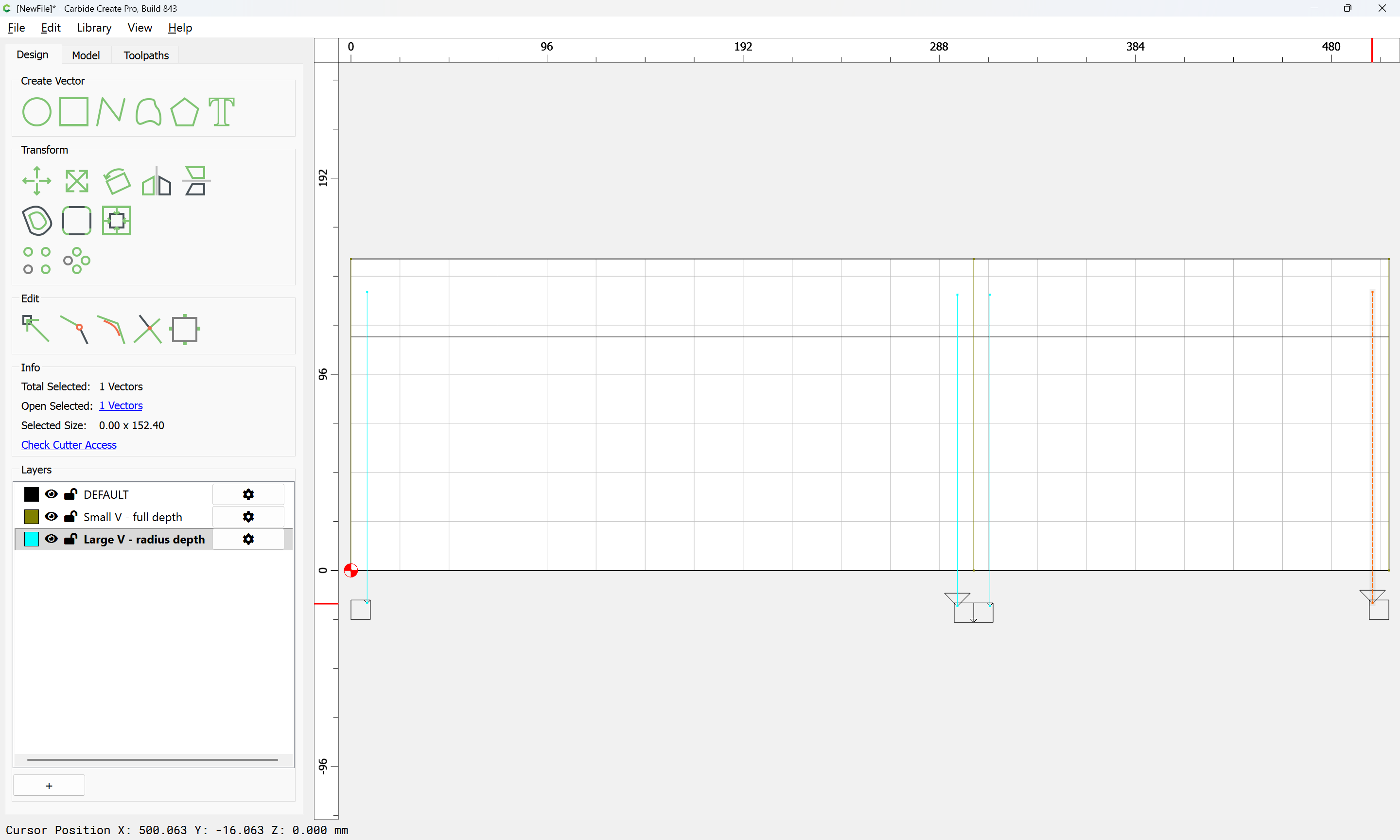
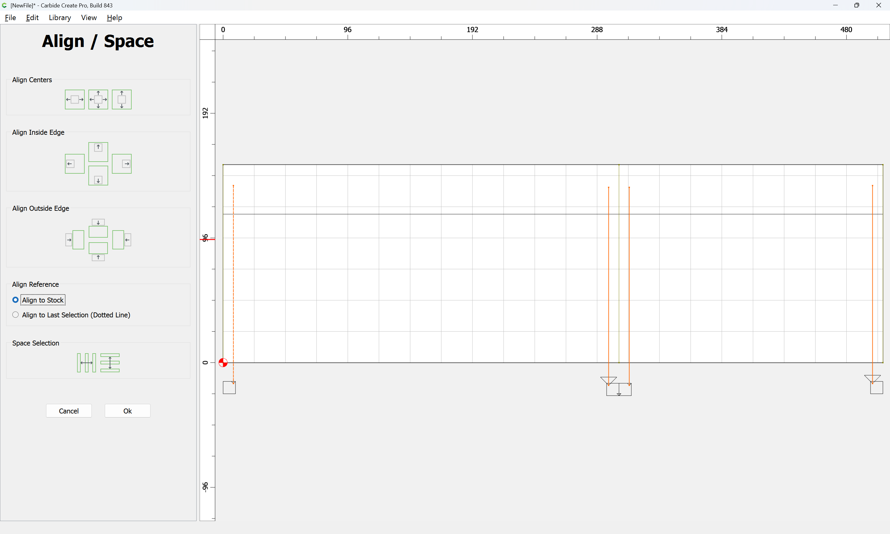
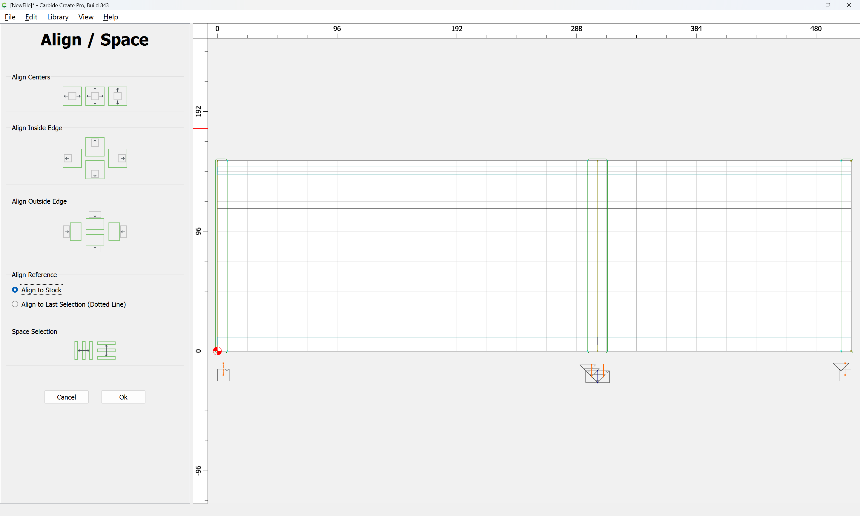
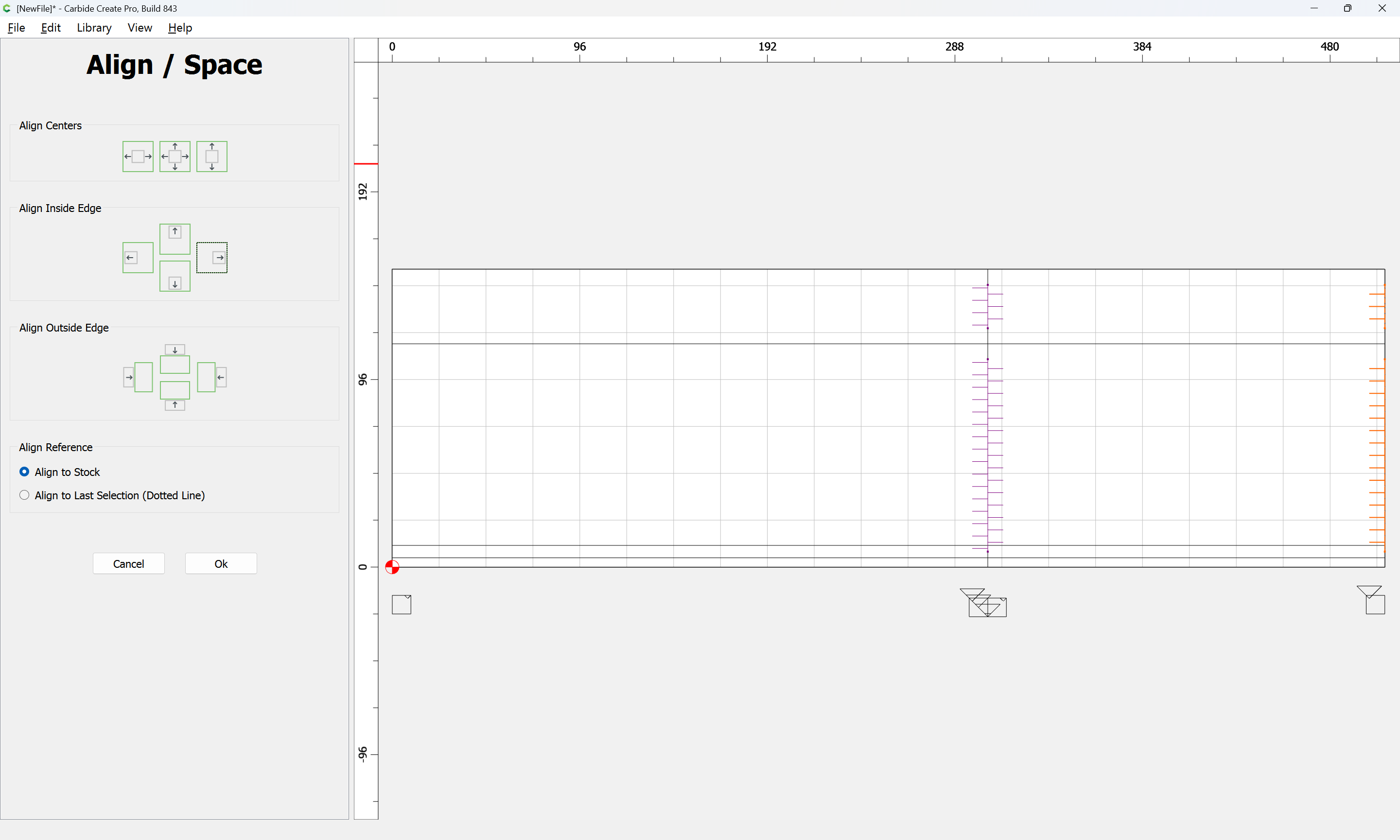
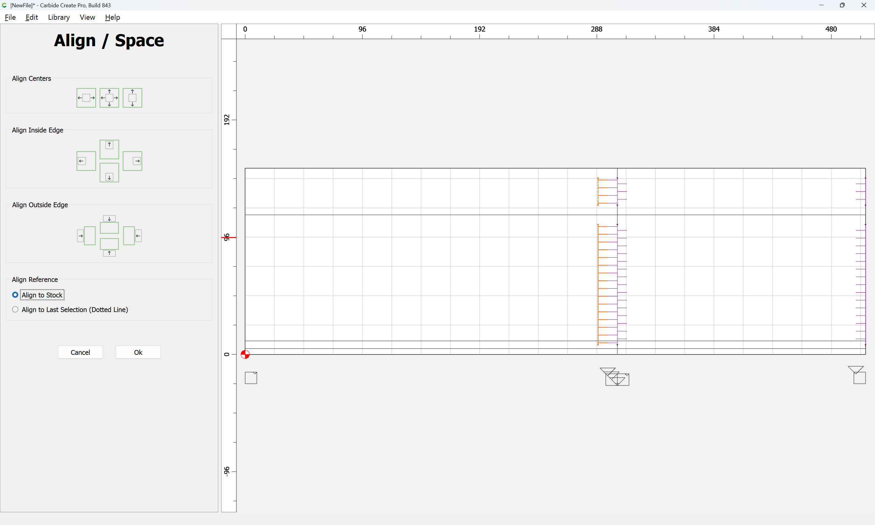
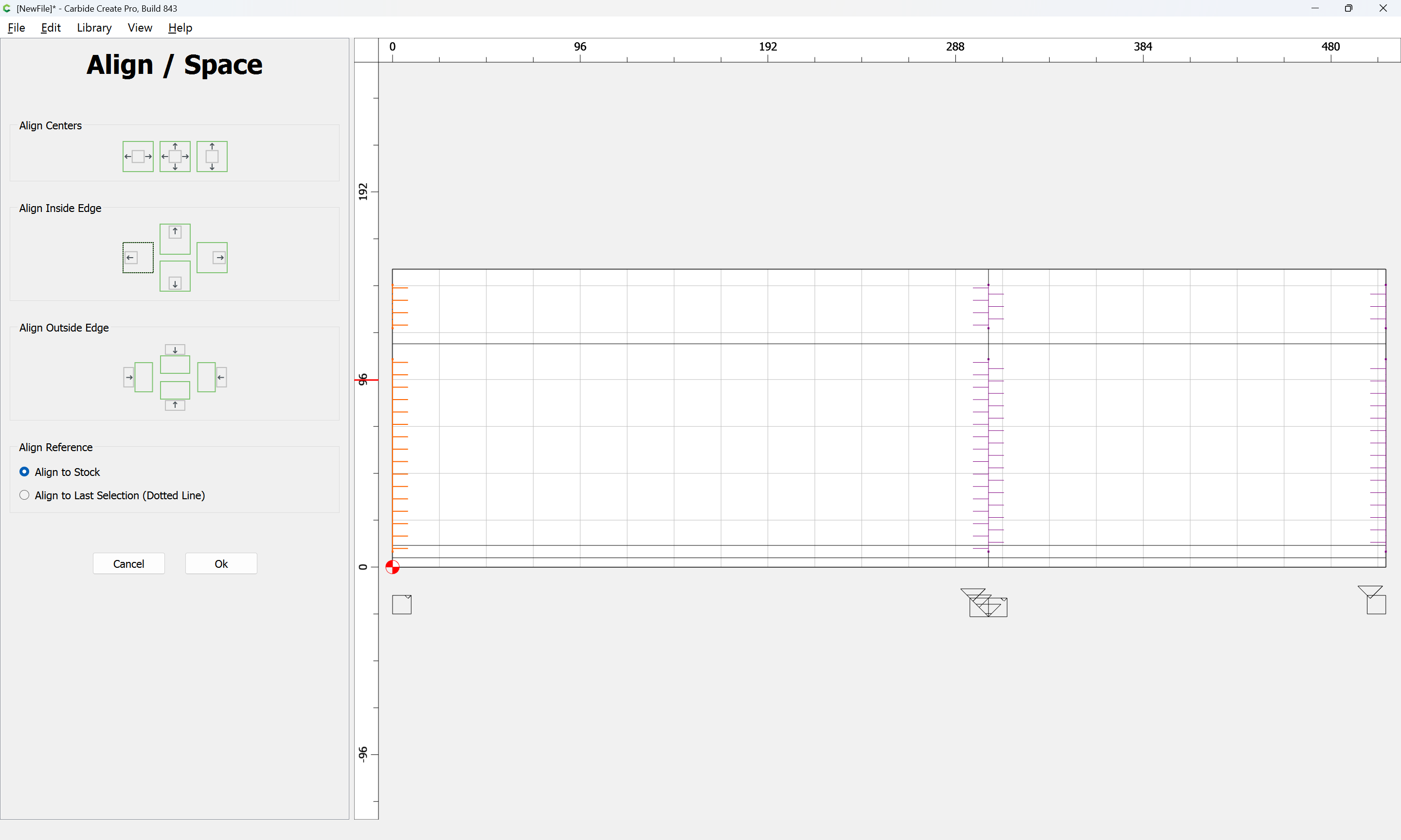
and then aligning with the stock:
OK

and make a suitable toolpath:
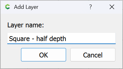
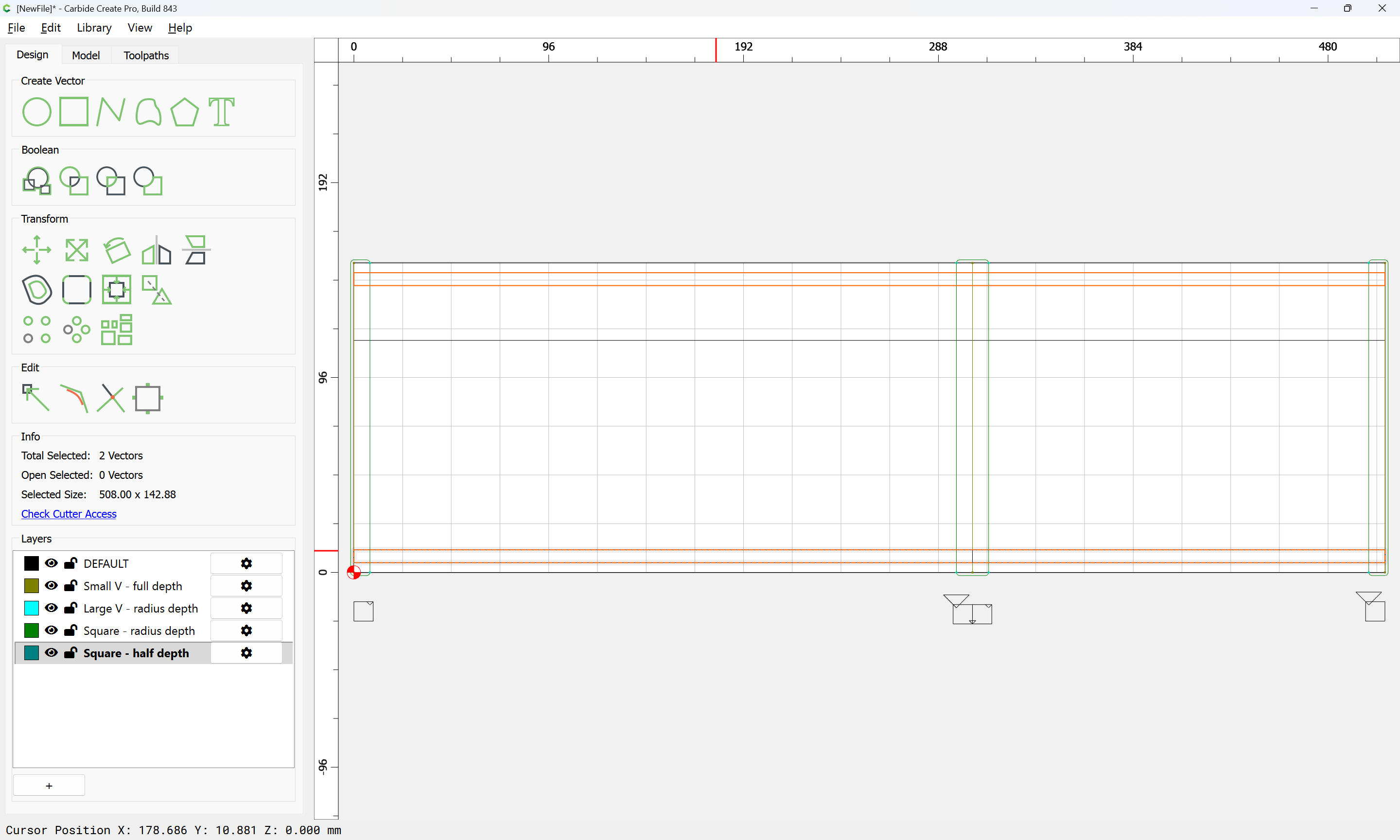
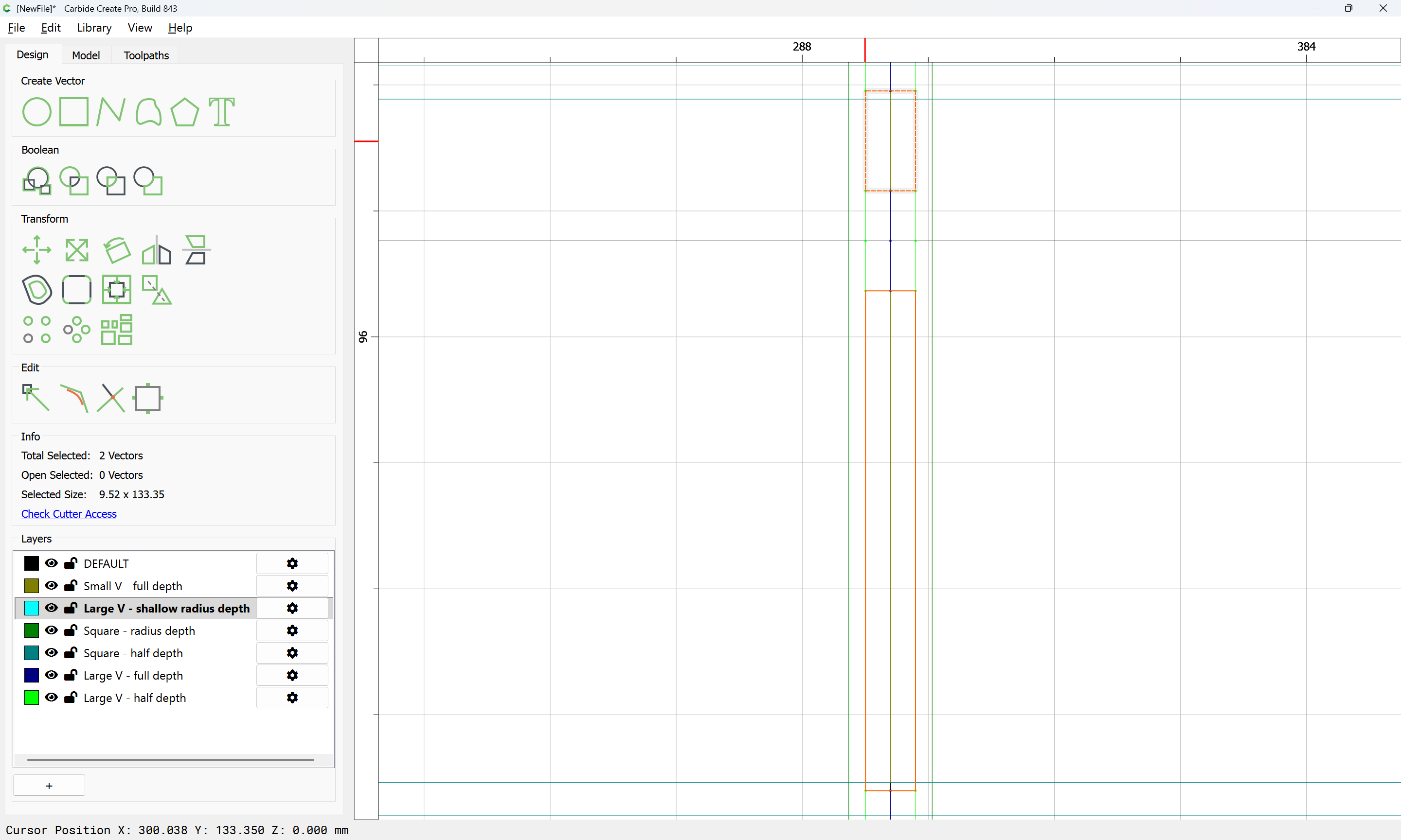
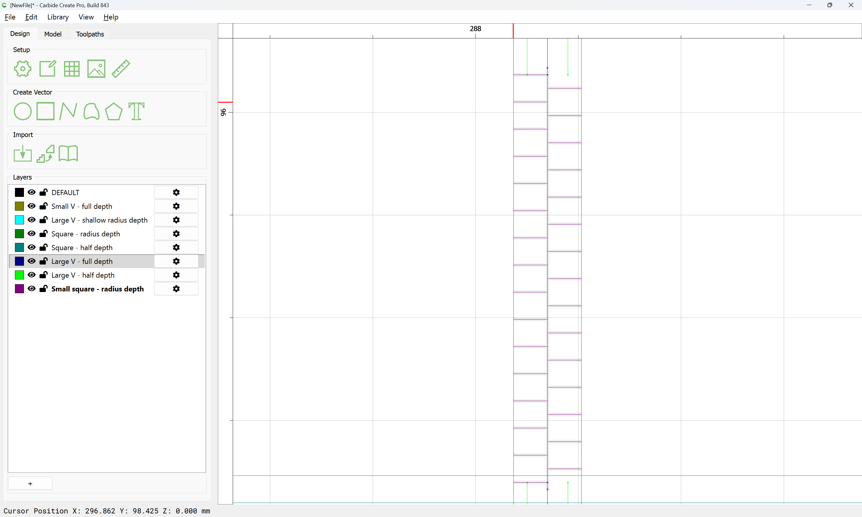
The area above the joints will also need to be cleared w/ a suitable square tool:
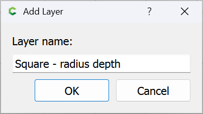
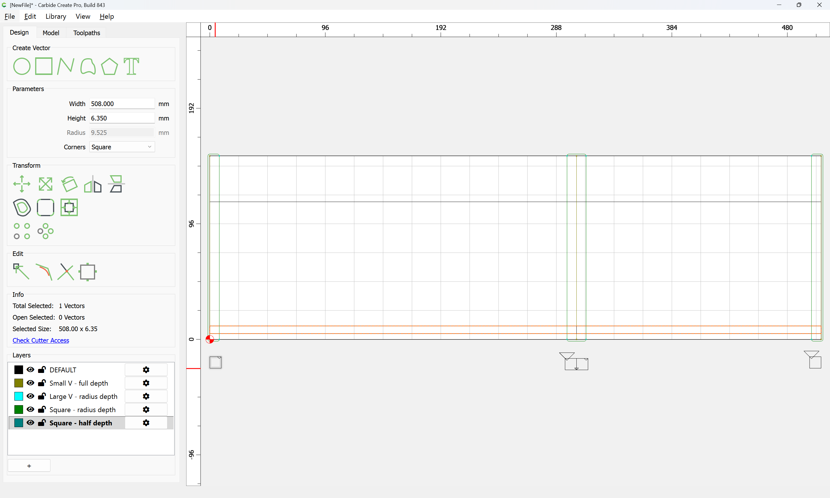
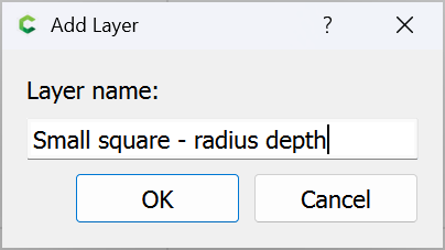
which will require another layer:
Increasing the height by the diameter of the tool to be used:
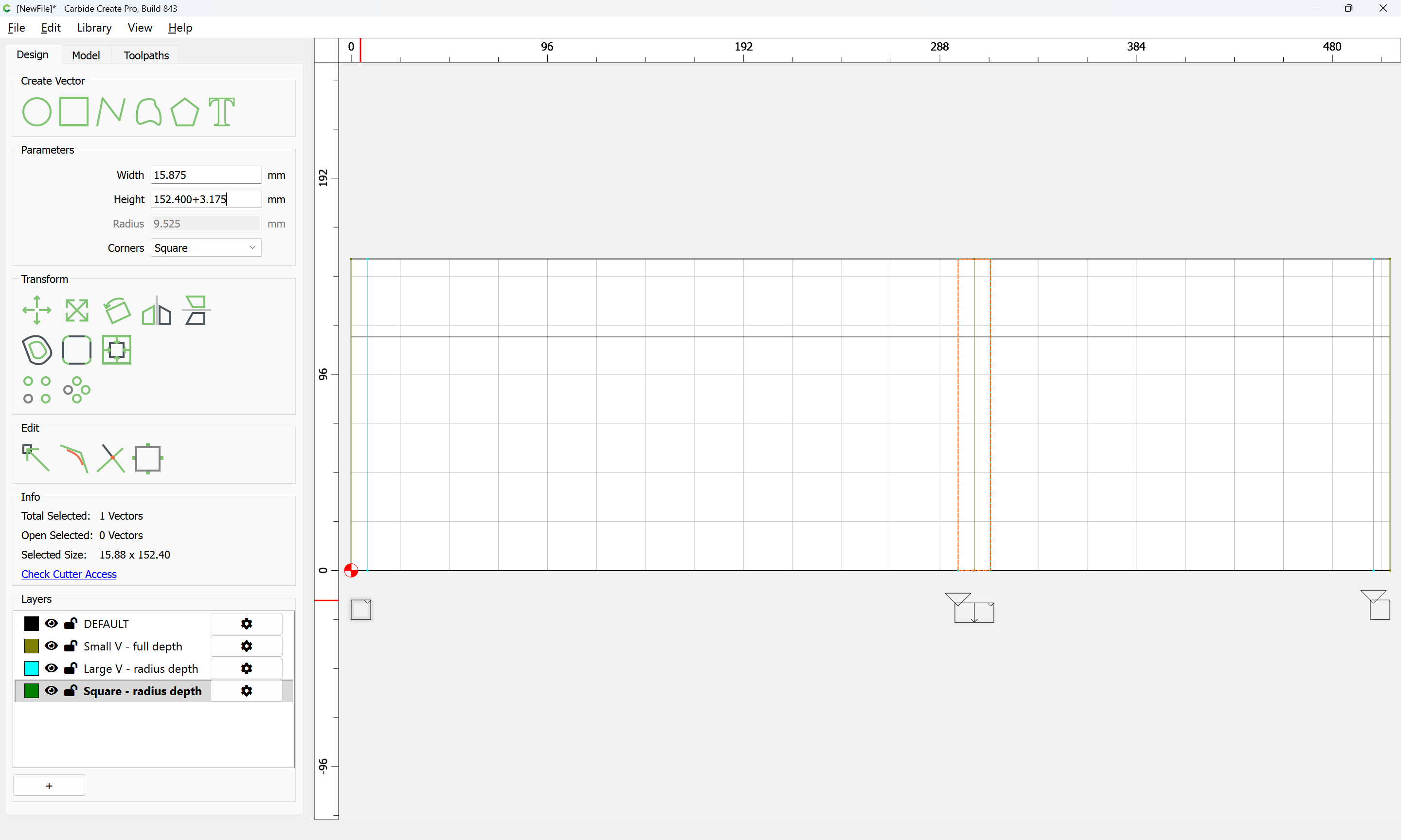

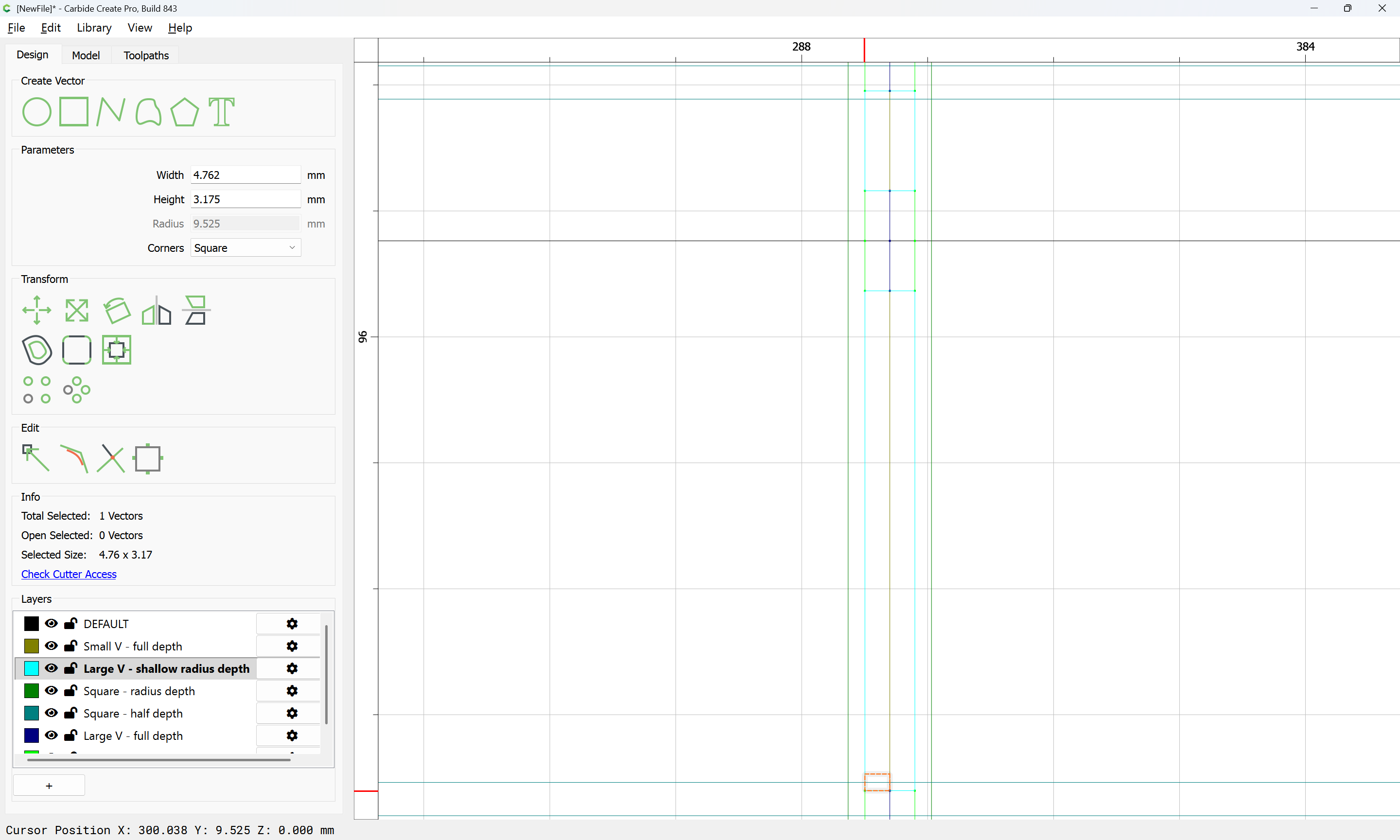
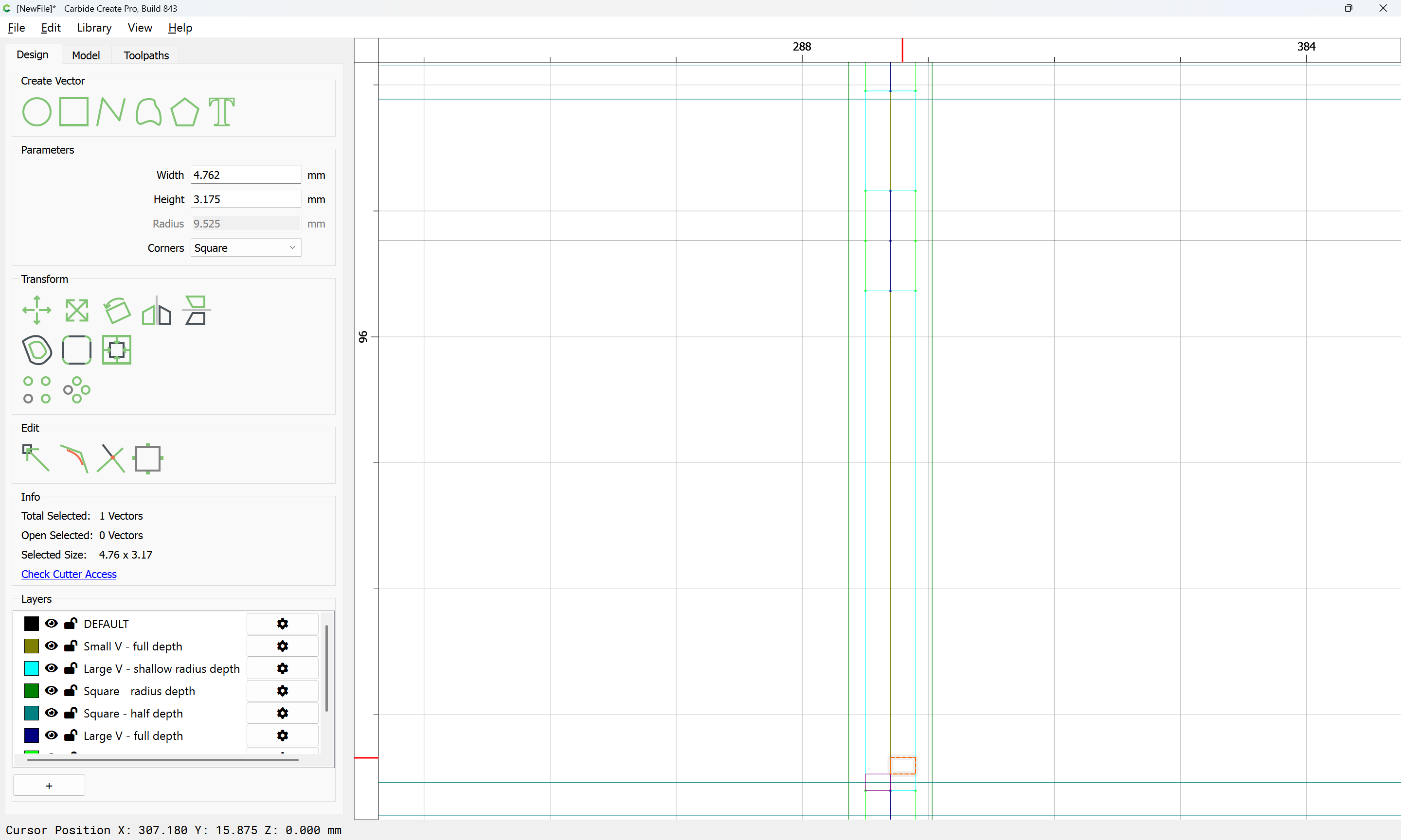
and then setting that radius:
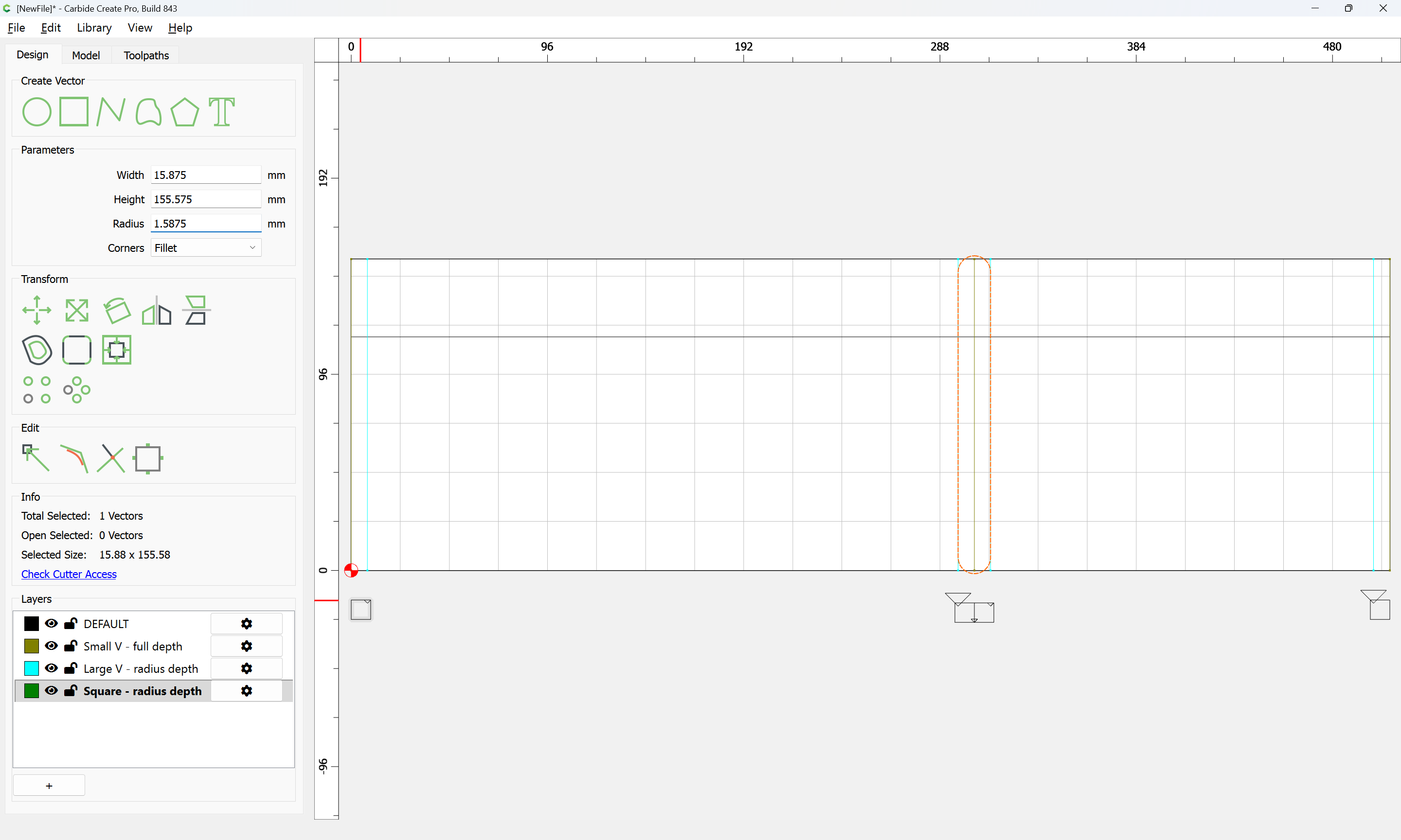
affords a handle for moving this in register:

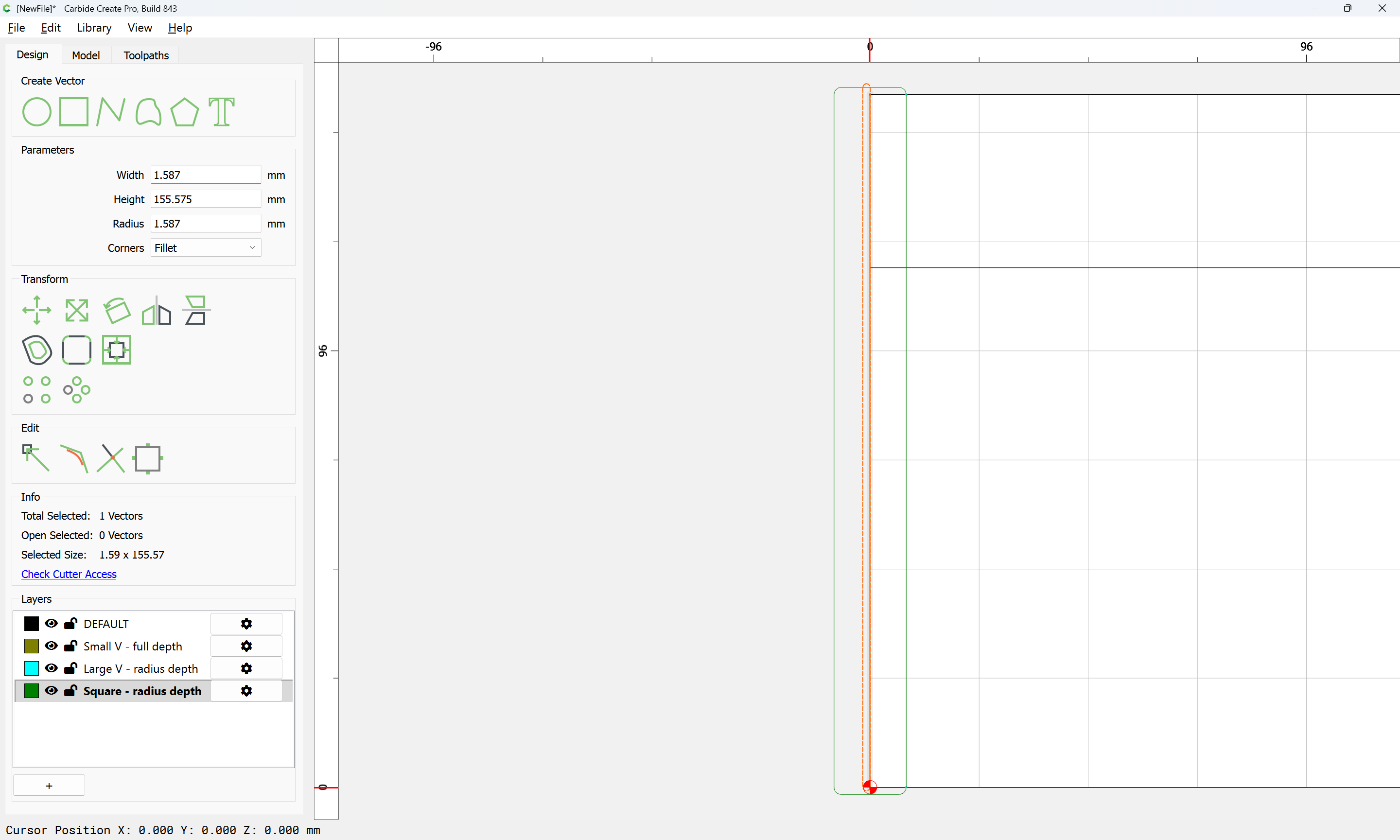
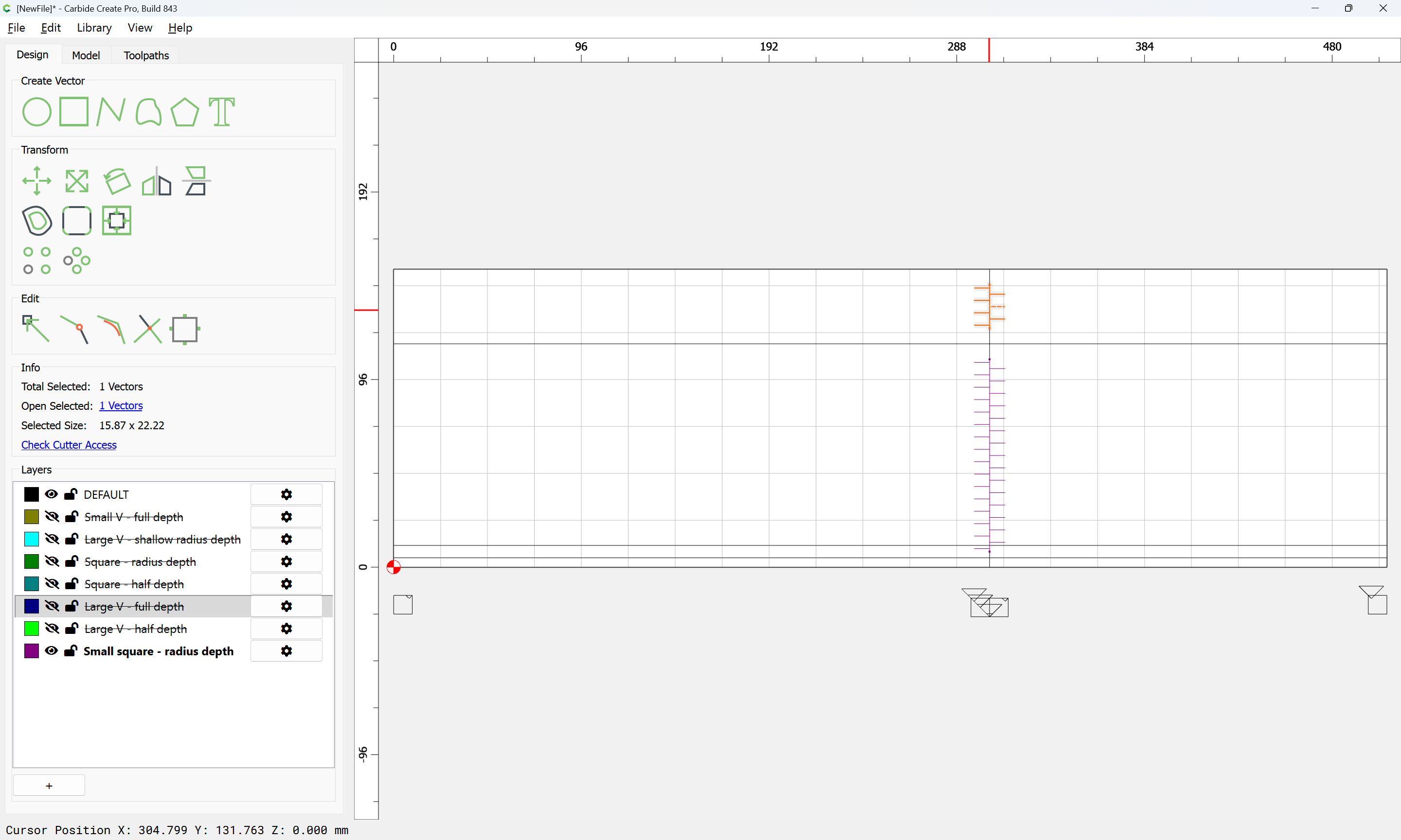
Note that these regions when cutting only one side of a joint may be trimmed down a bit:
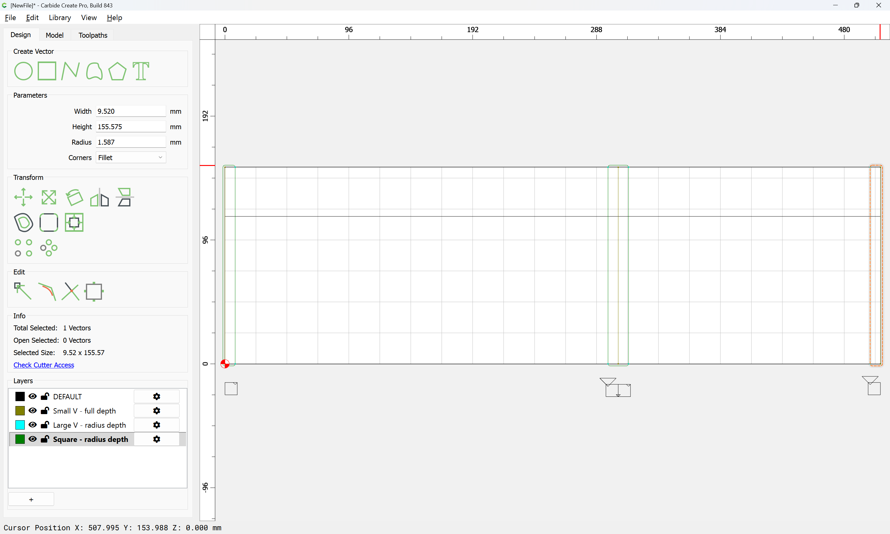
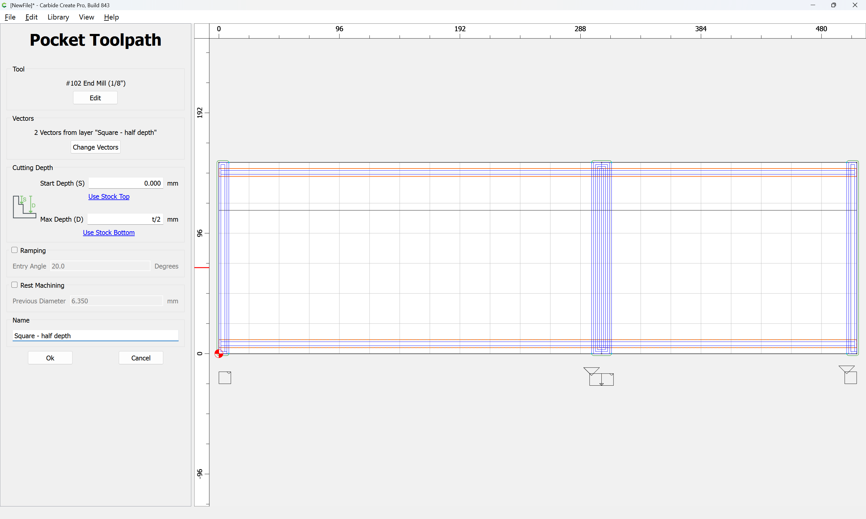
with all being assigned a suitable toolpath:
Also using a square tool will be the grooves for the top/bottom:
The balance of the toolpaths will be for the joinery, or, just in case the stock is not the exact height of the box, cutting the top/bottom of the stock free…
2 Likes
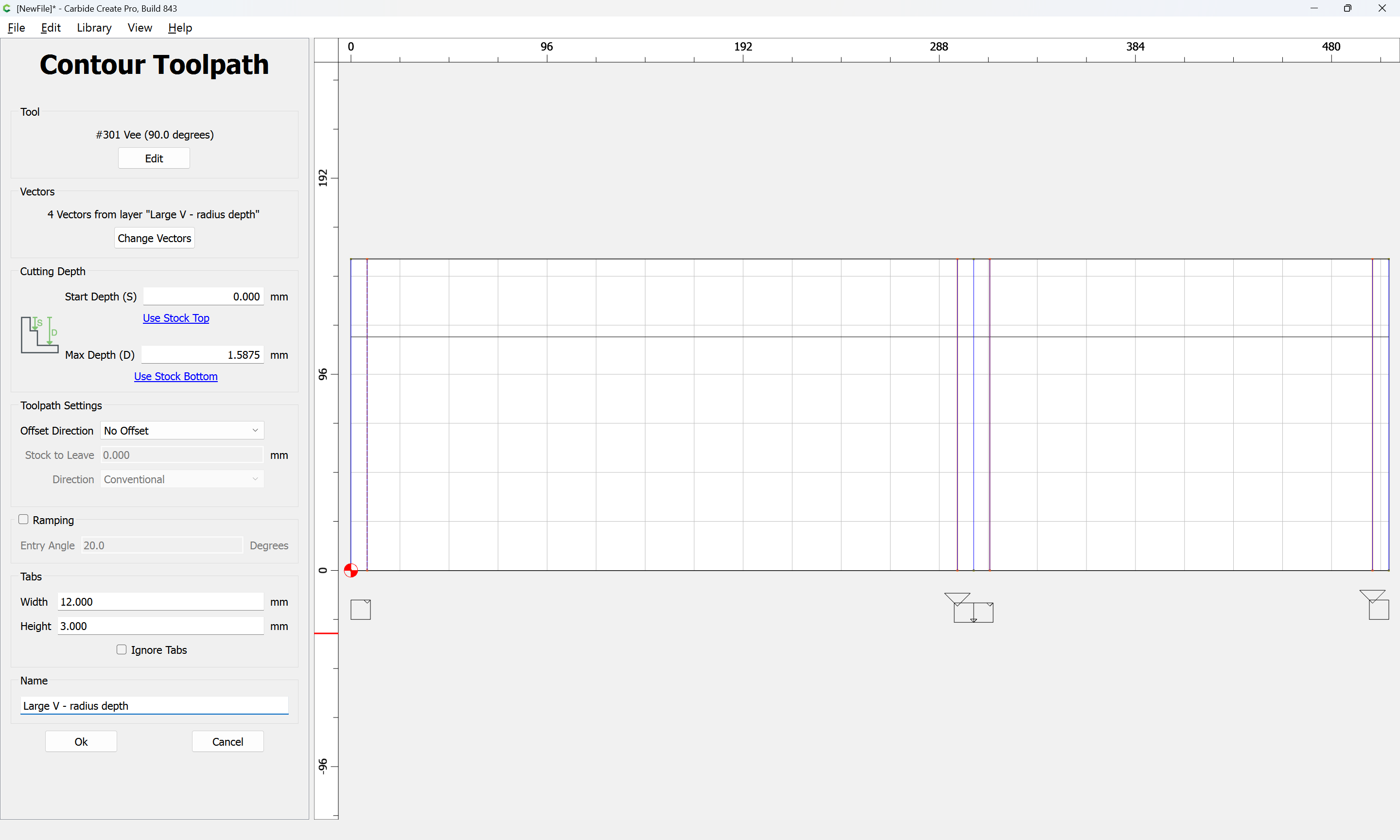
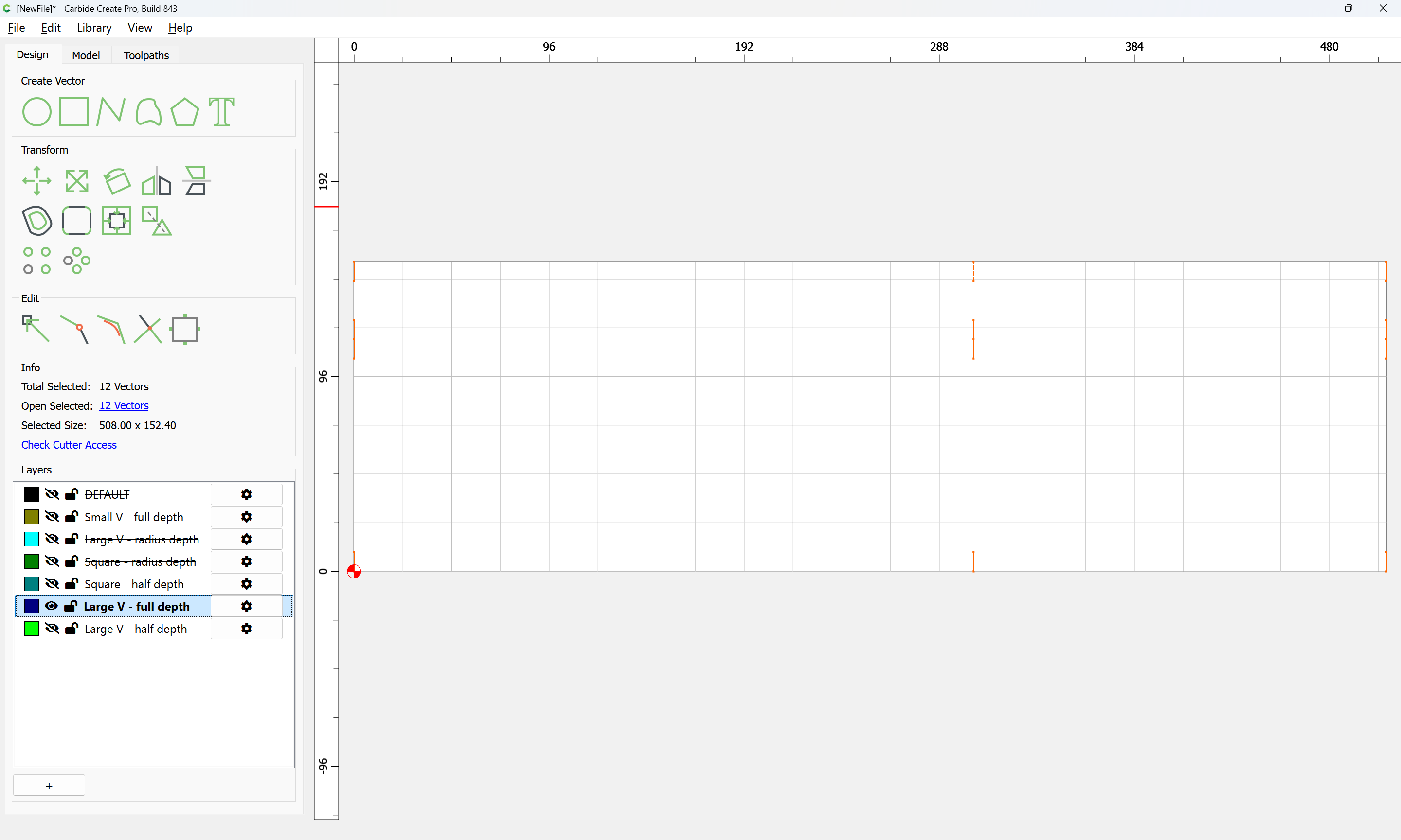
It is simplest to use a large V tool to make the cuts at each end of the joint which make this full-blind:
If the stock is thicker than the large V tool can cut, then a second toolpath will be necessary:

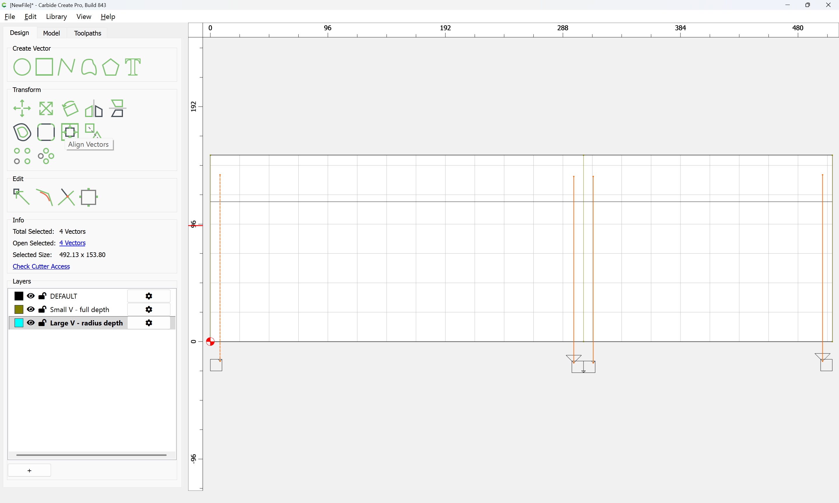
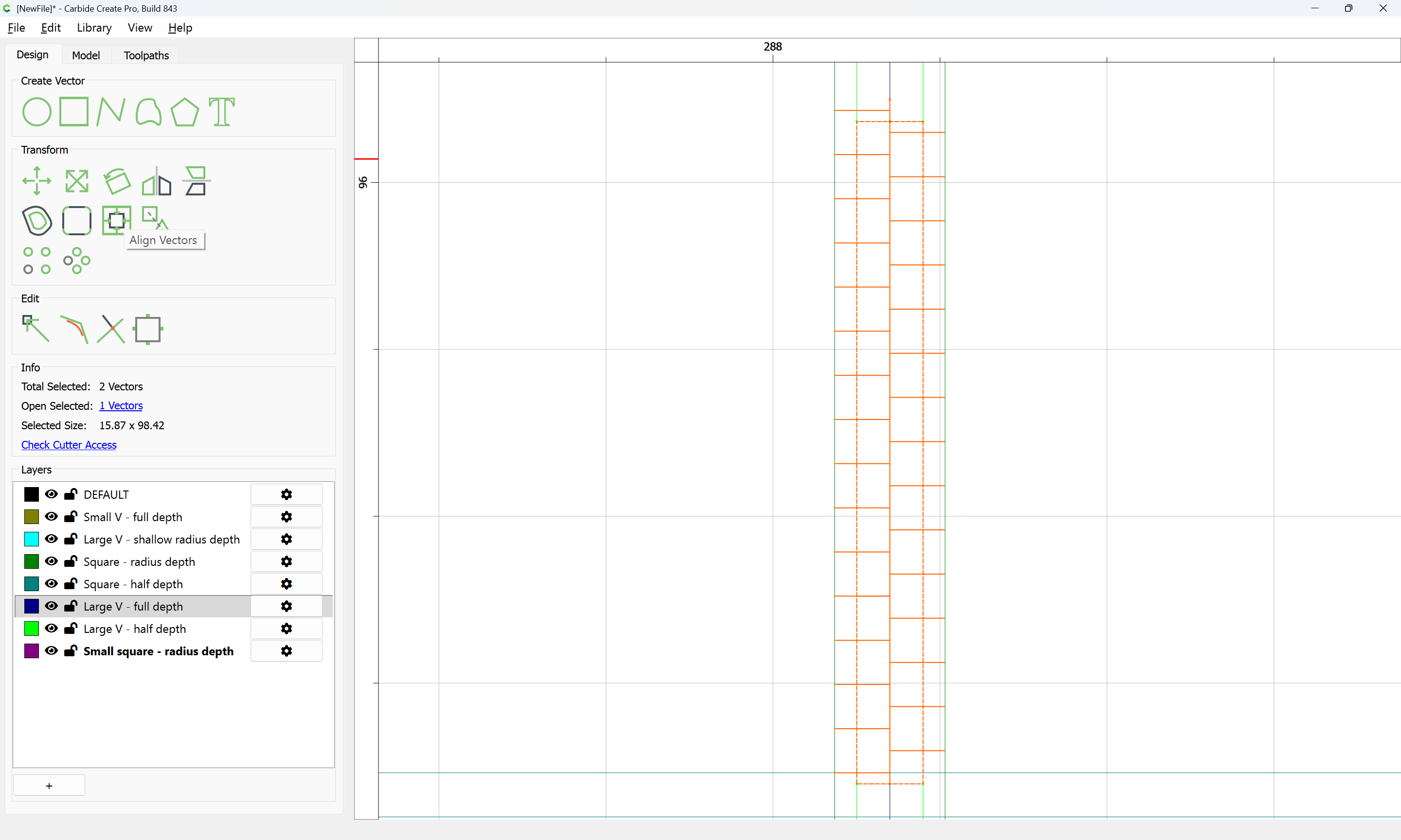
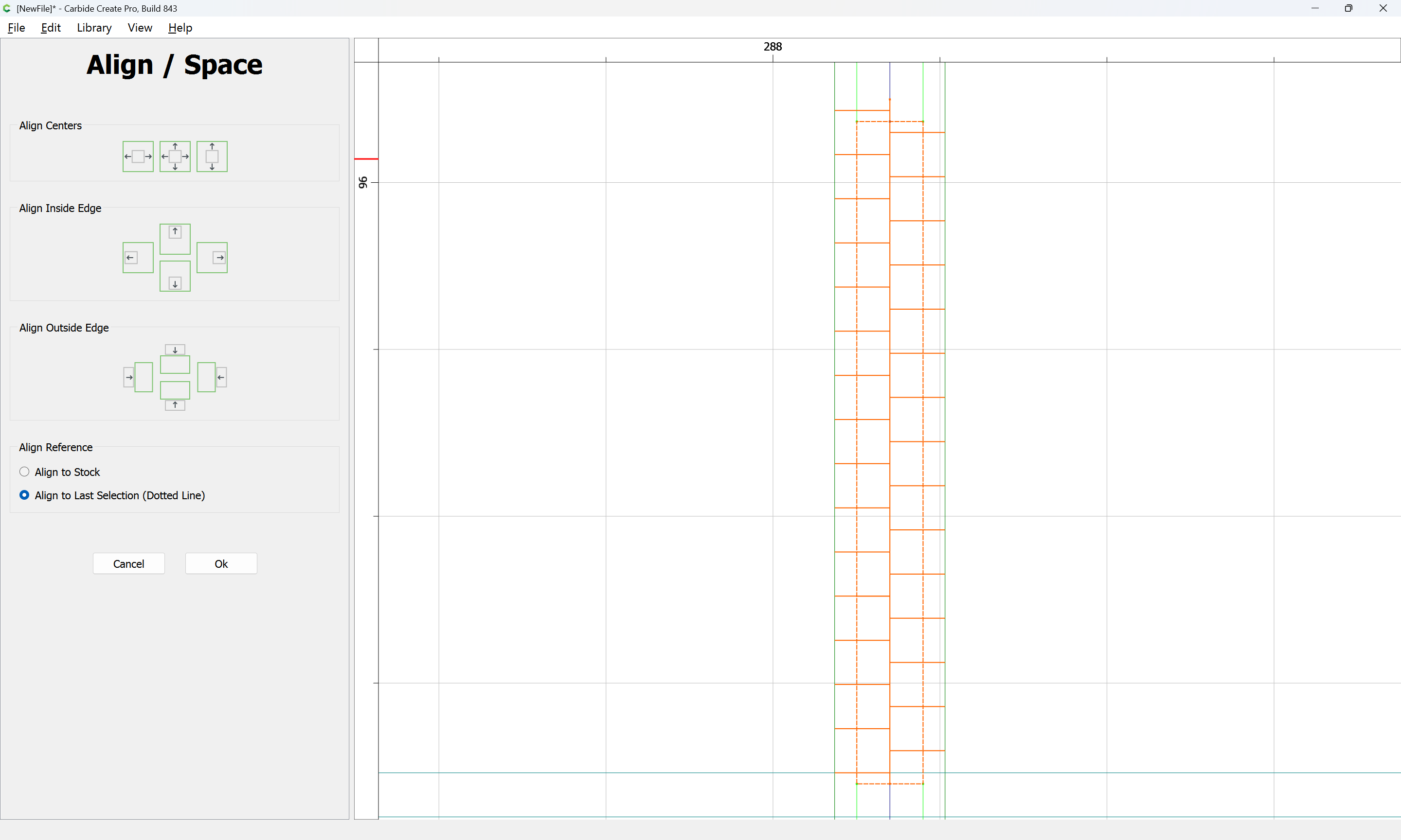
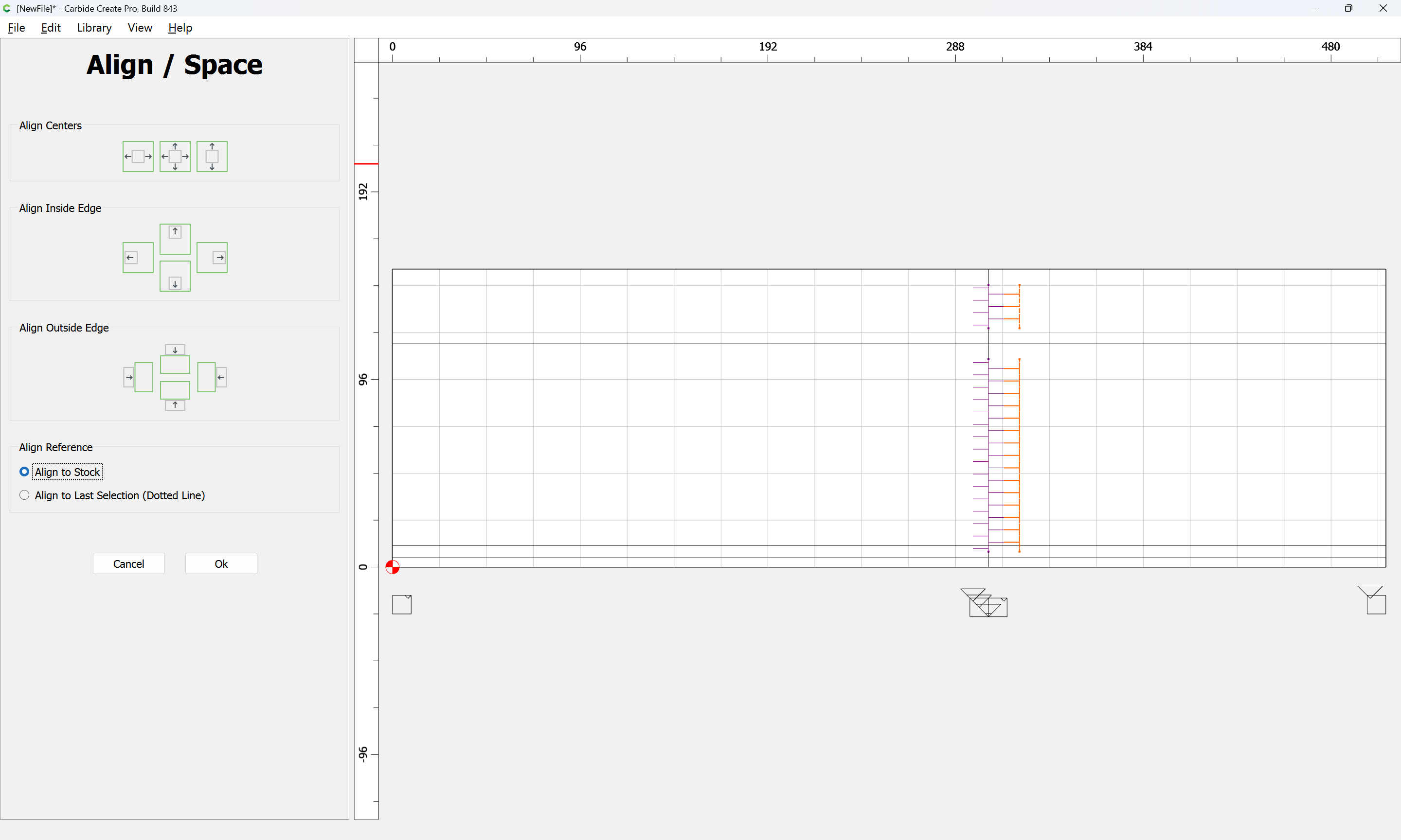
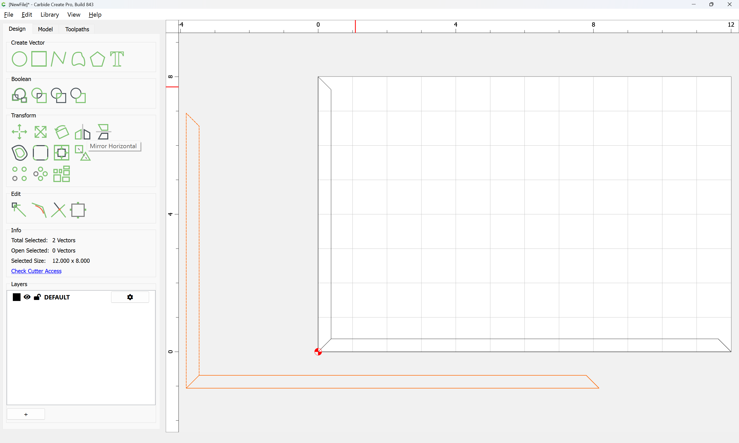
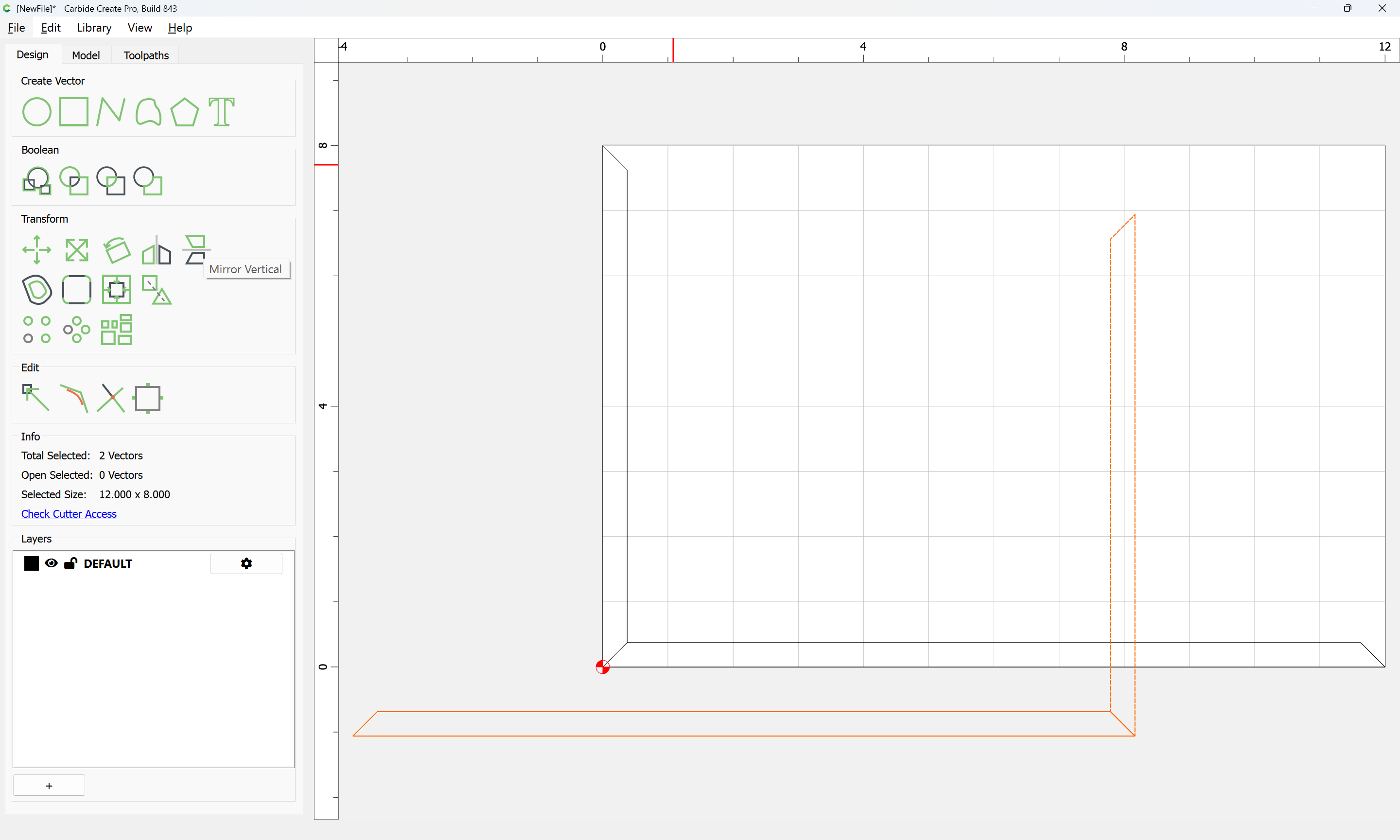
Once all are drawn, then they may be selected:
aligned:
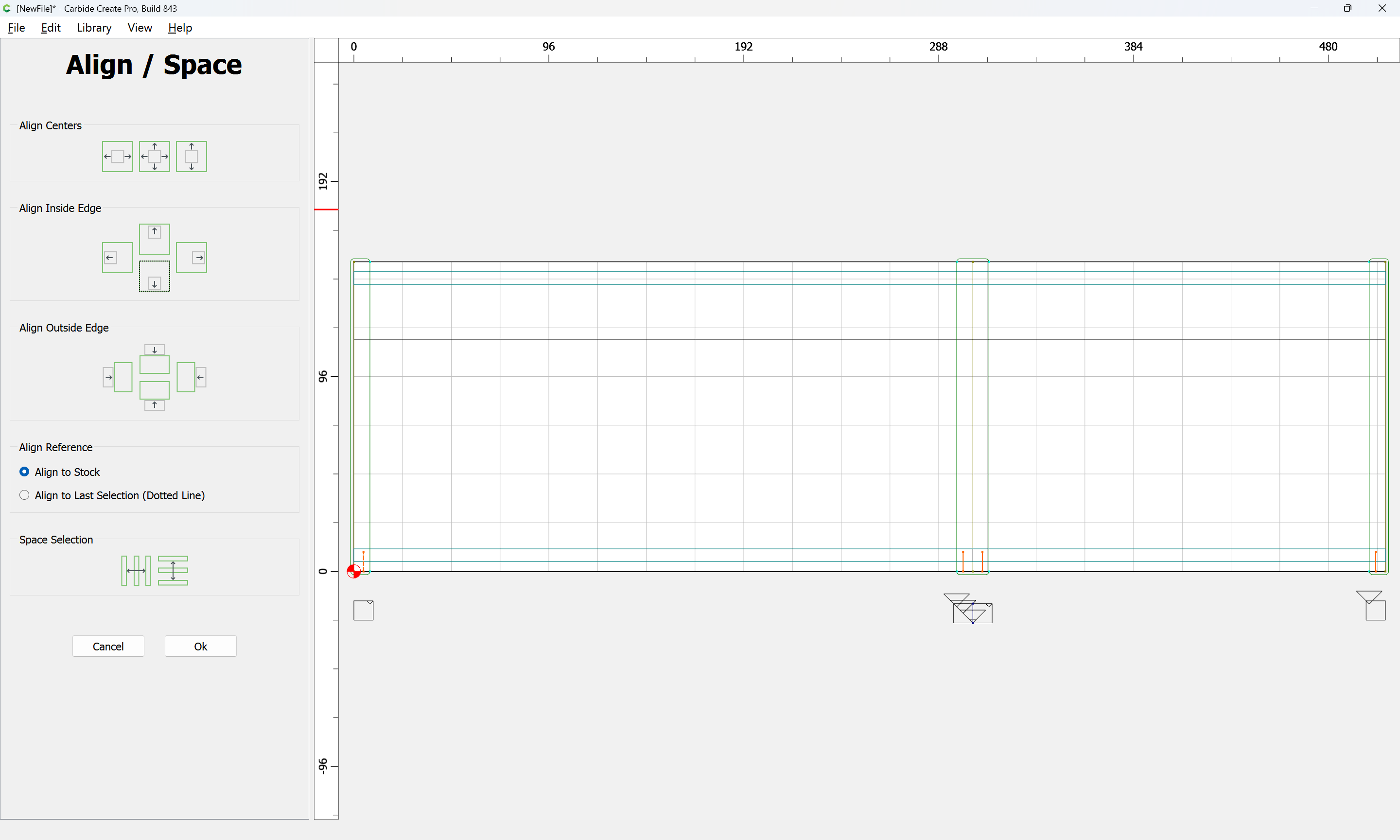
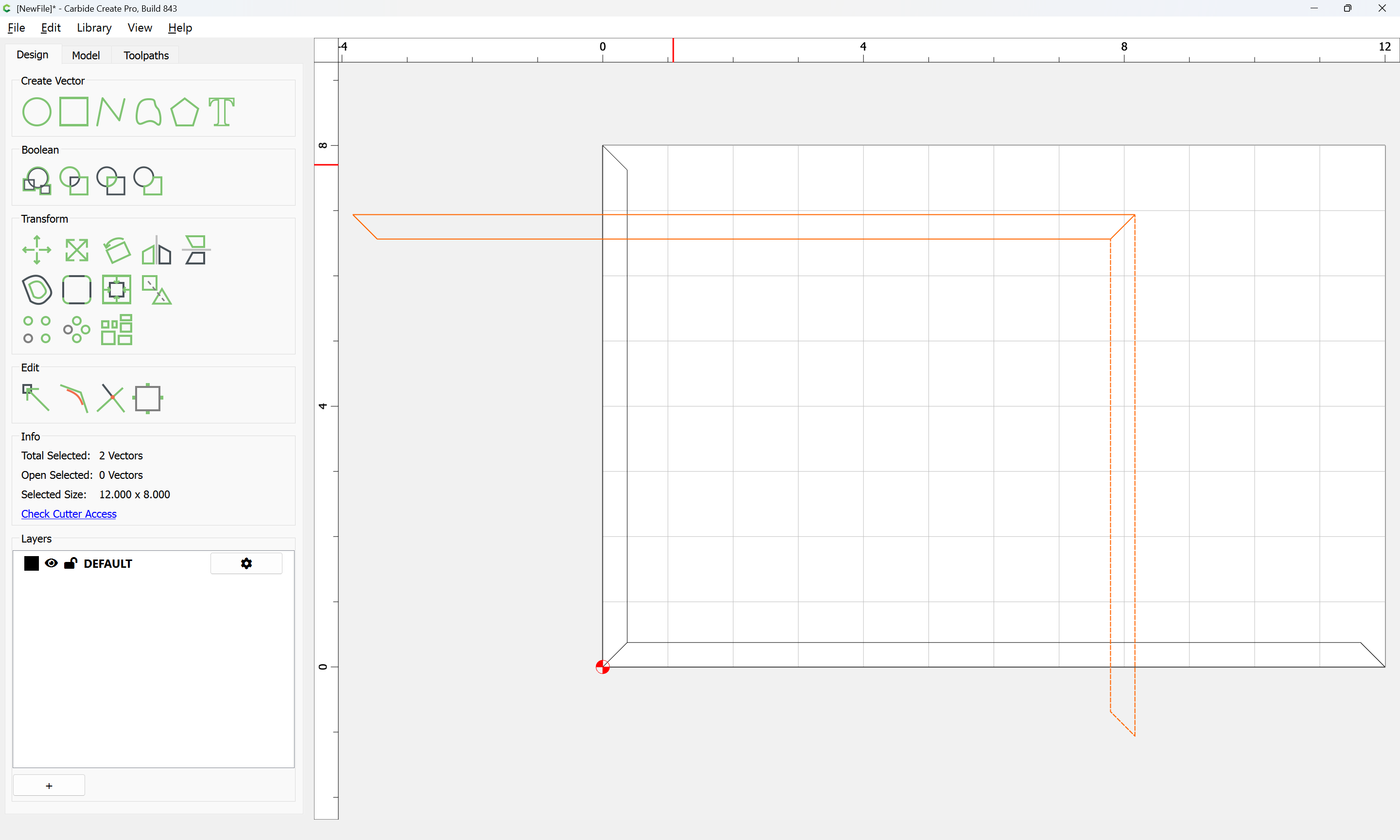
and duplicated and positioned as necessary:
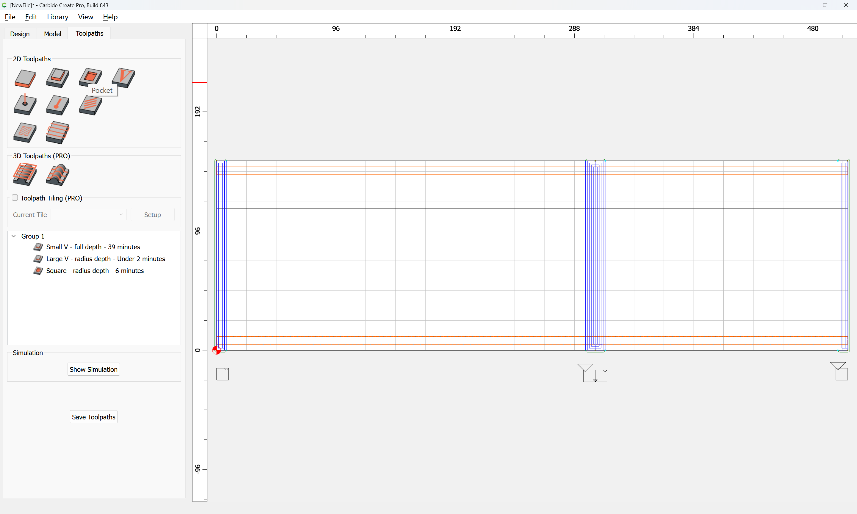
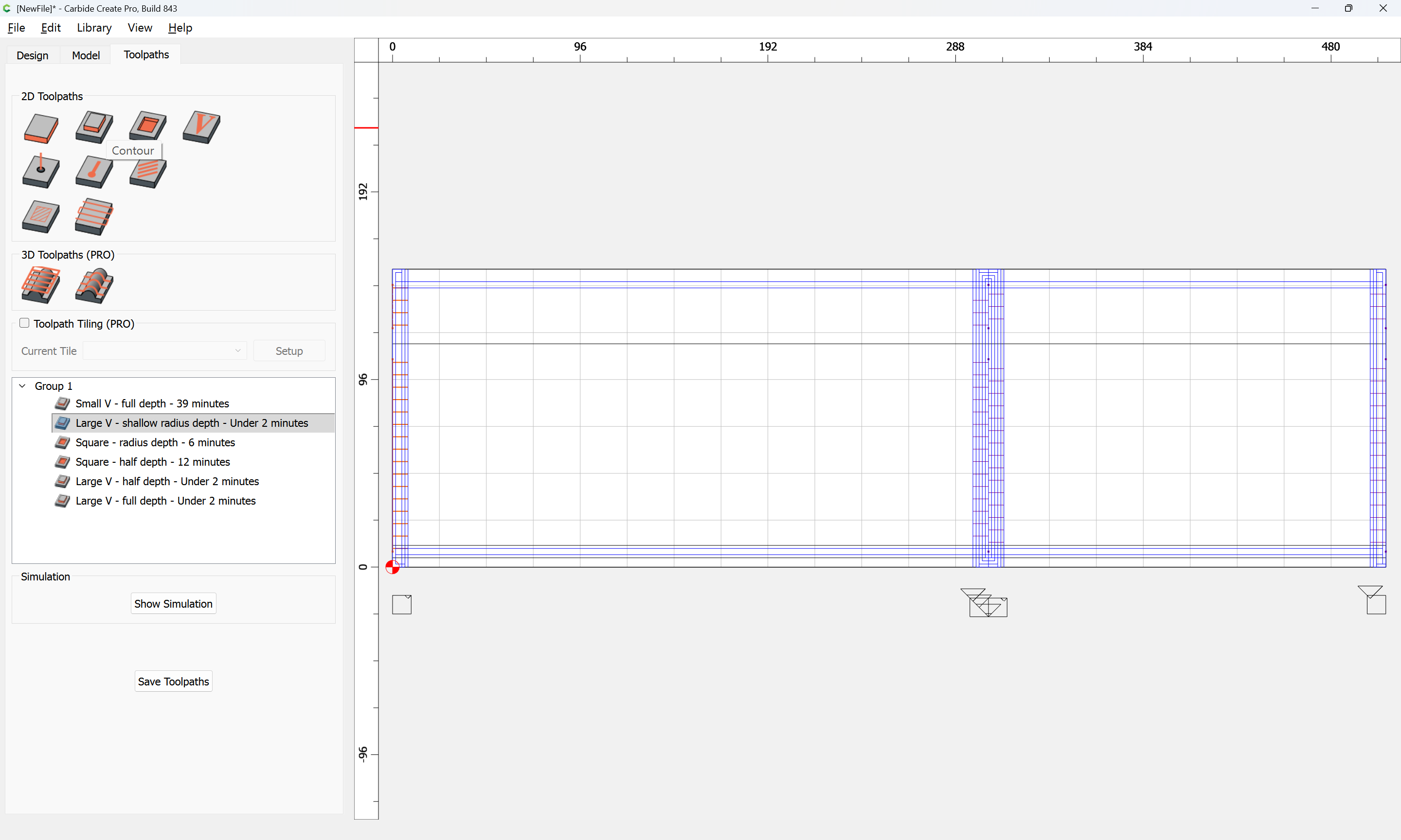
Then toolpaths assigned:
and a matching set of toolpaths made for the full depth cuts with the V tool:
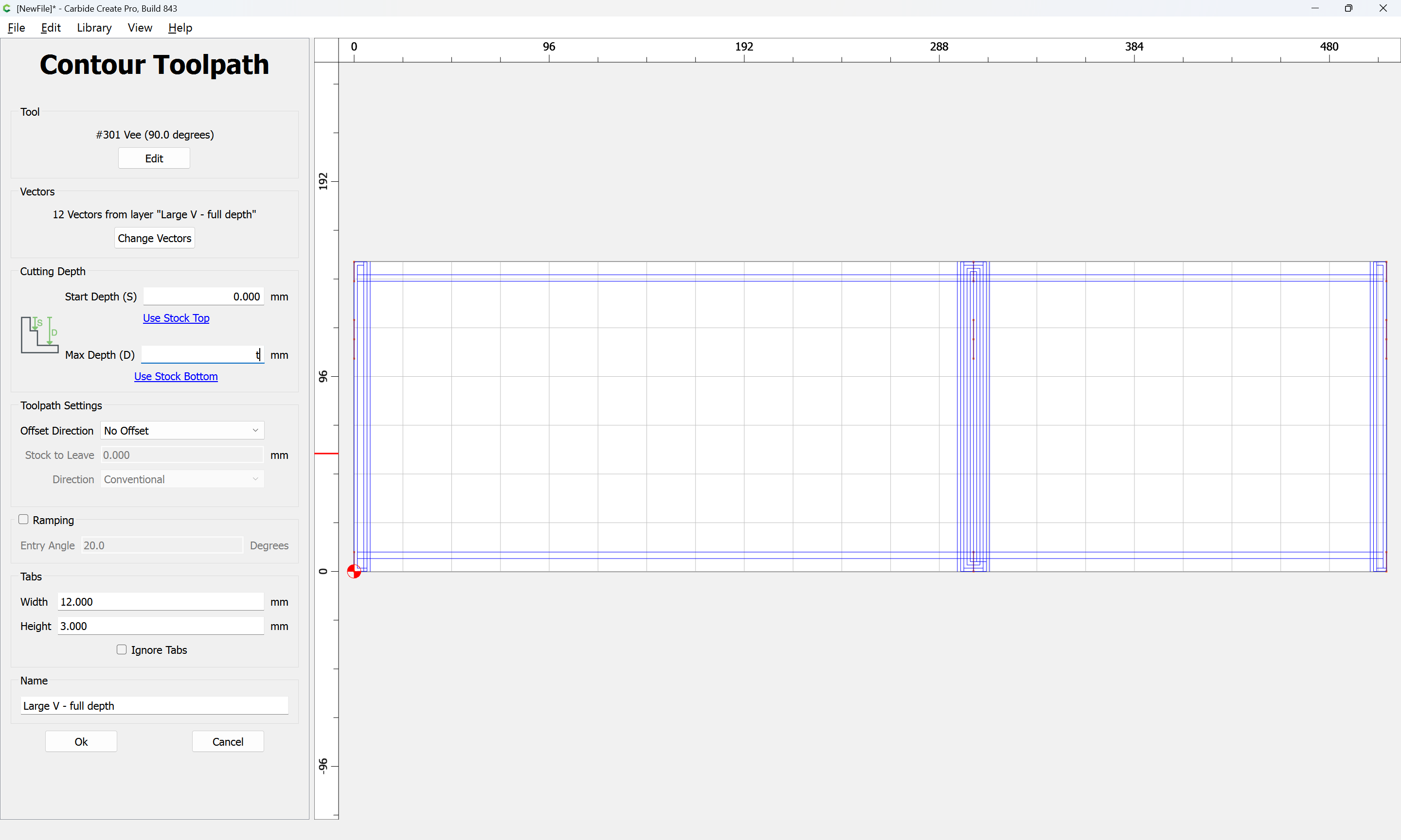
which all previews as:
leaving just cutting the actual joints…
2 Likes
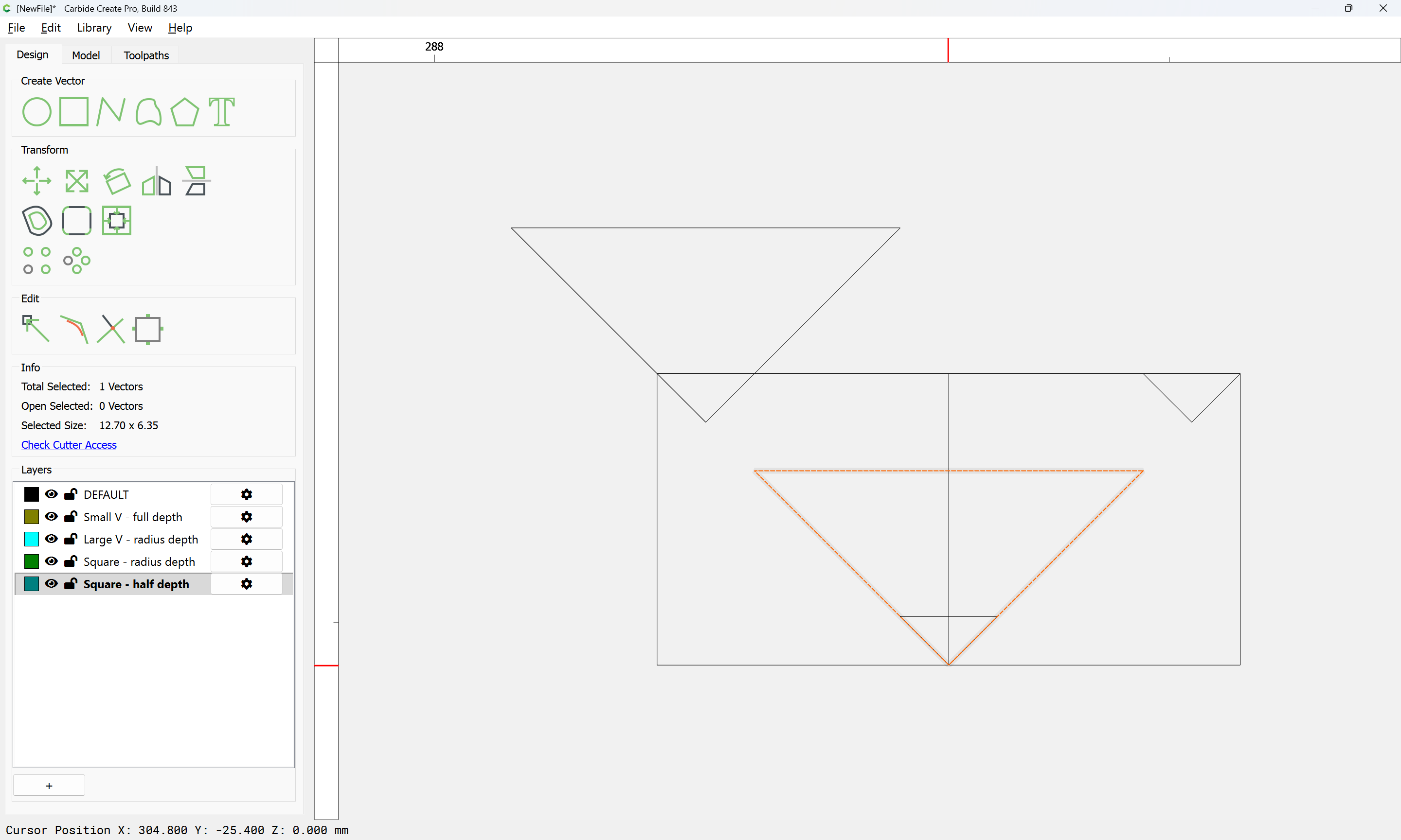
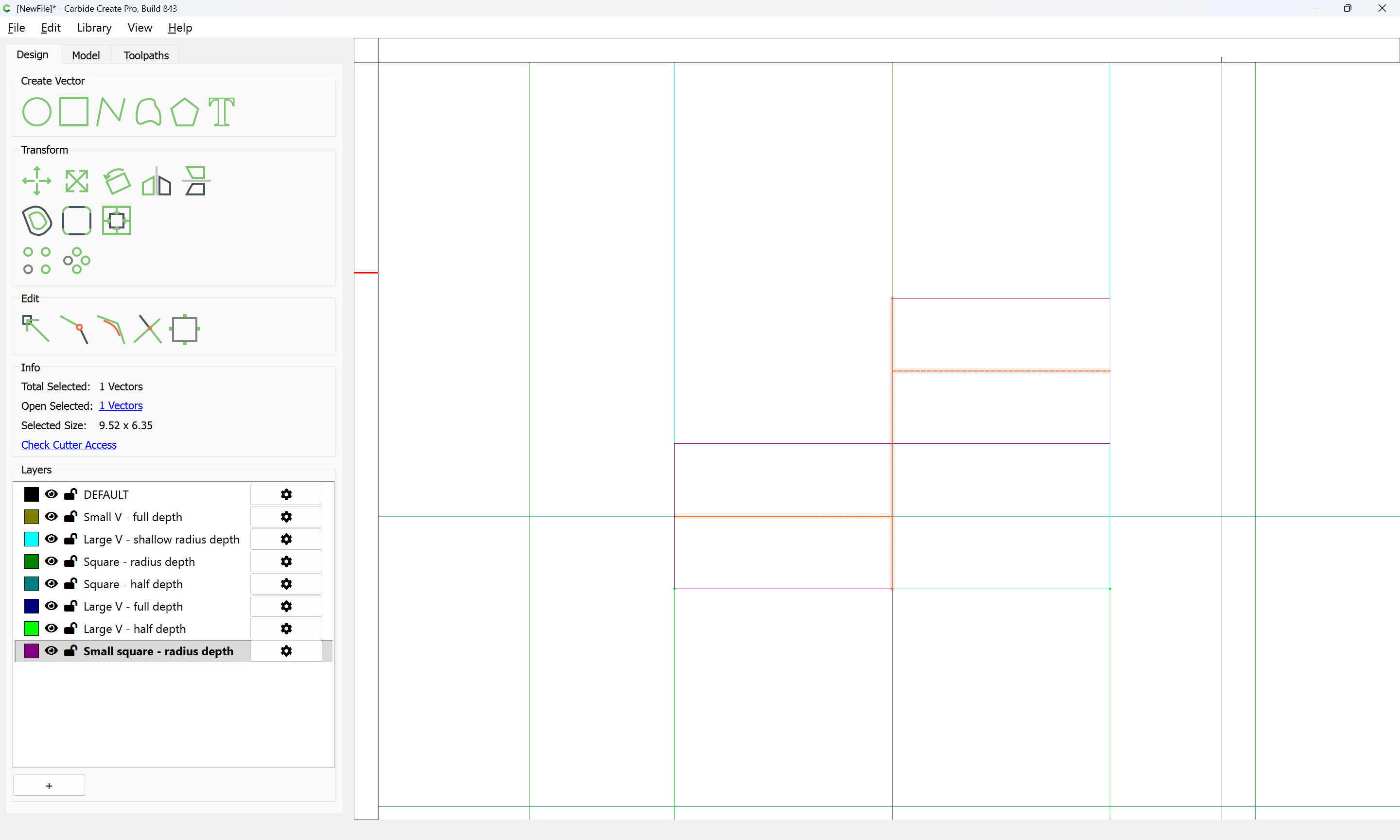
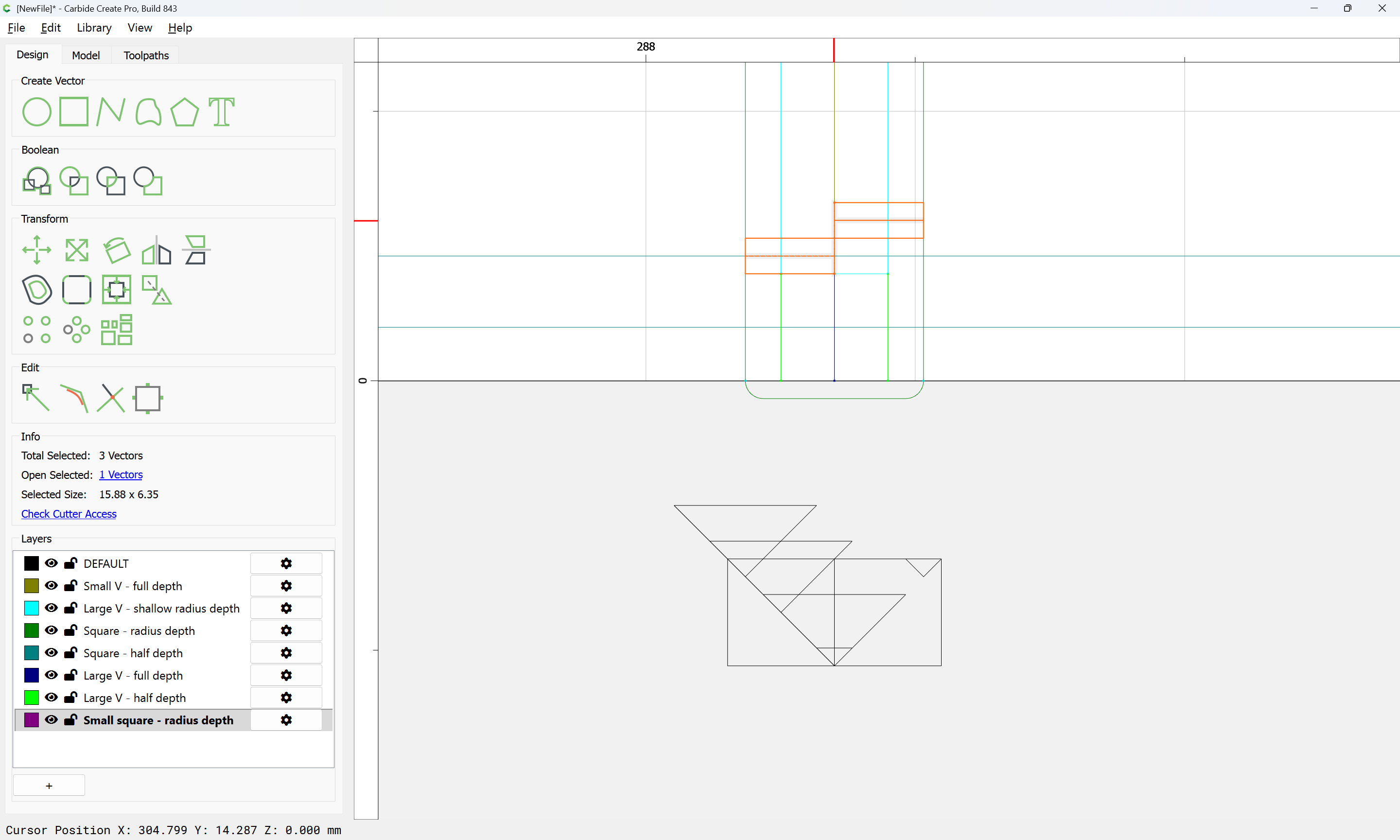
Cutting the actual joinery requires filling two regions:
with an alternating series of paths.
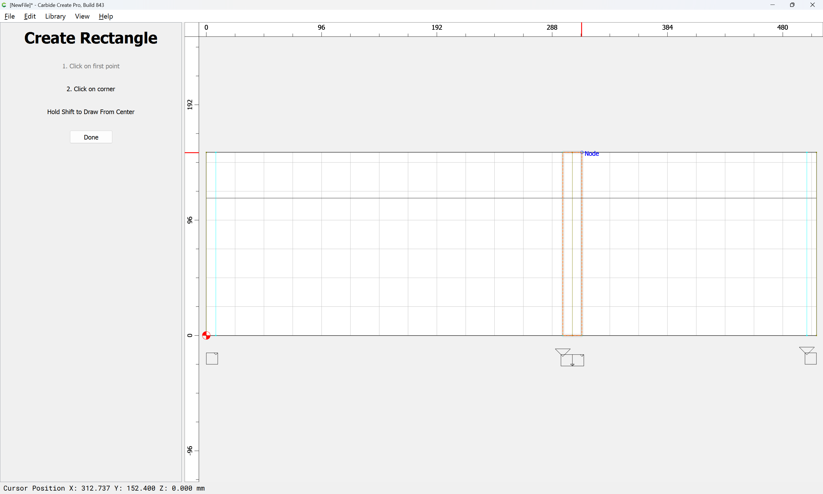
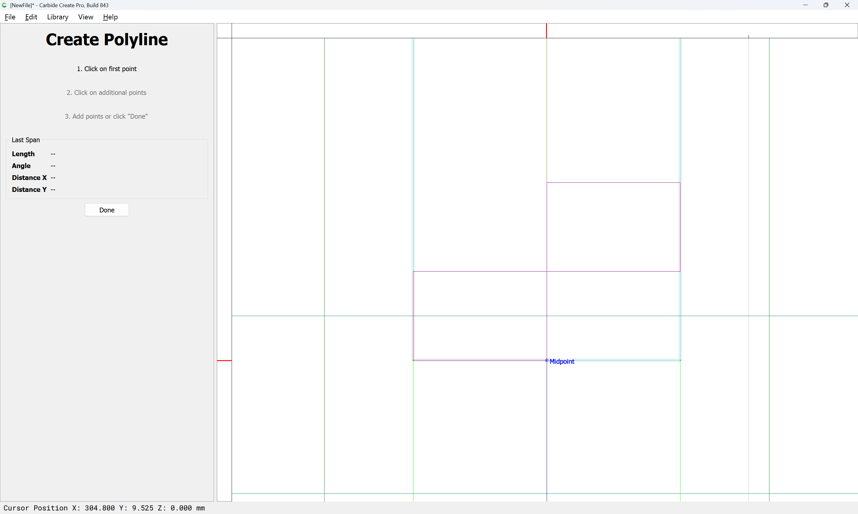
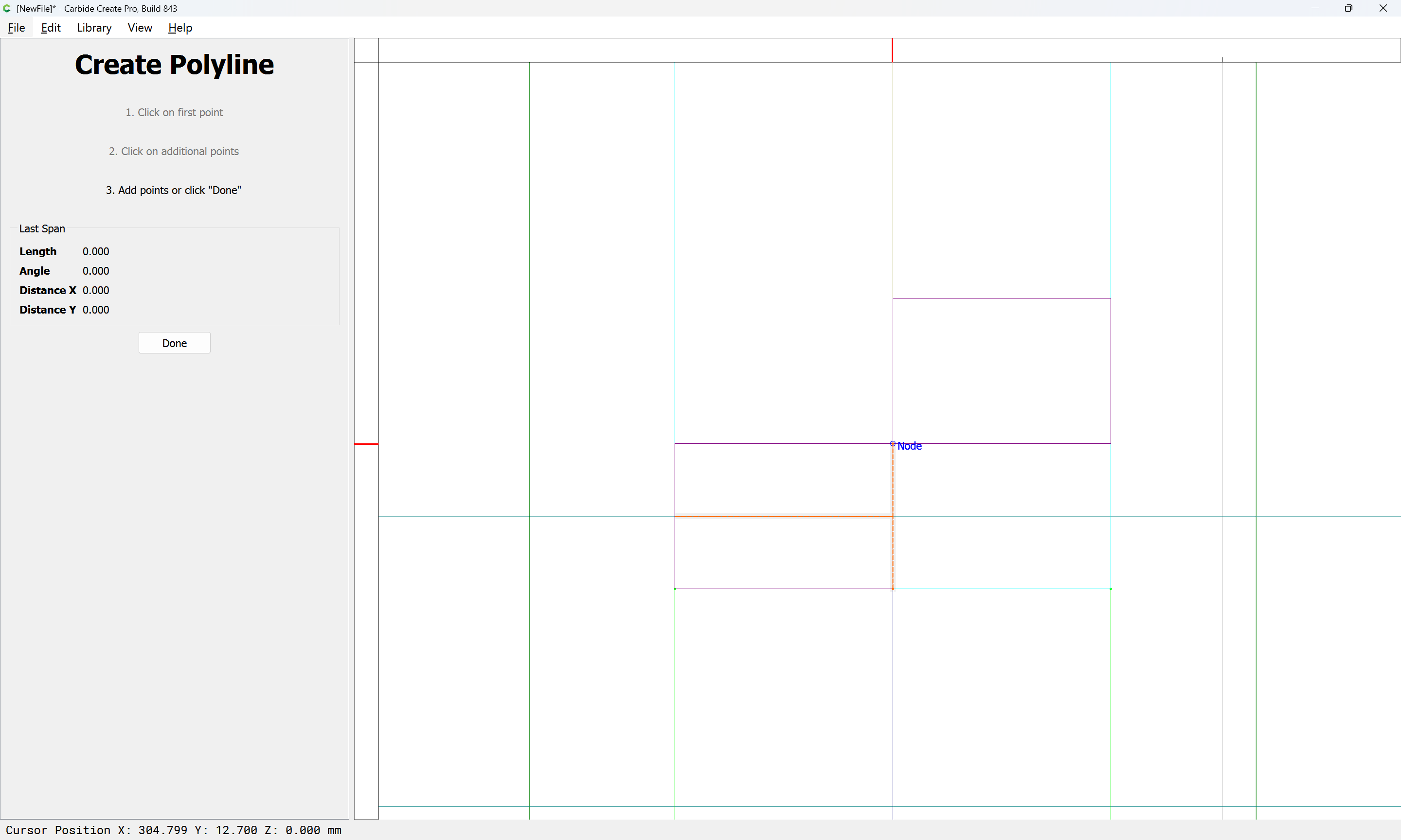
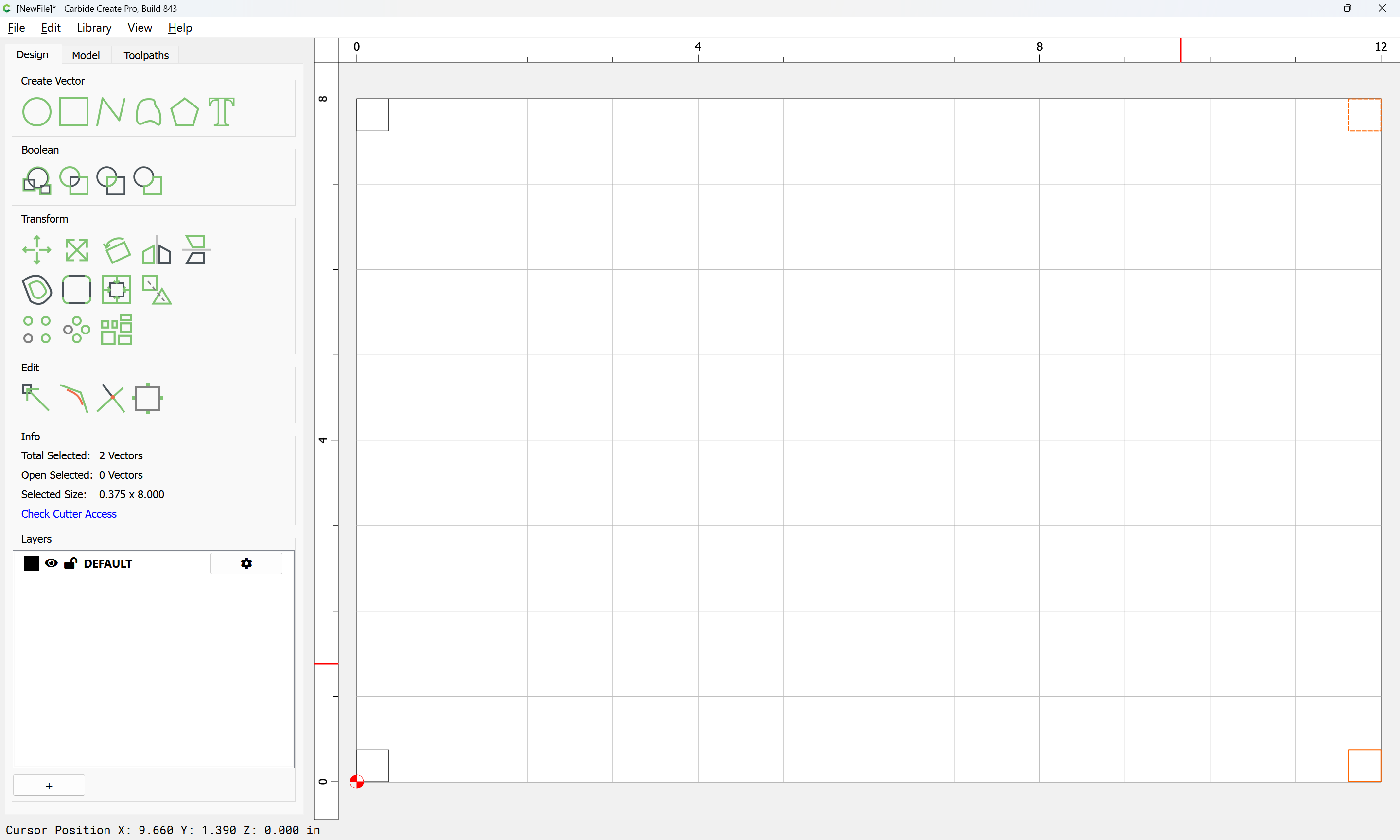
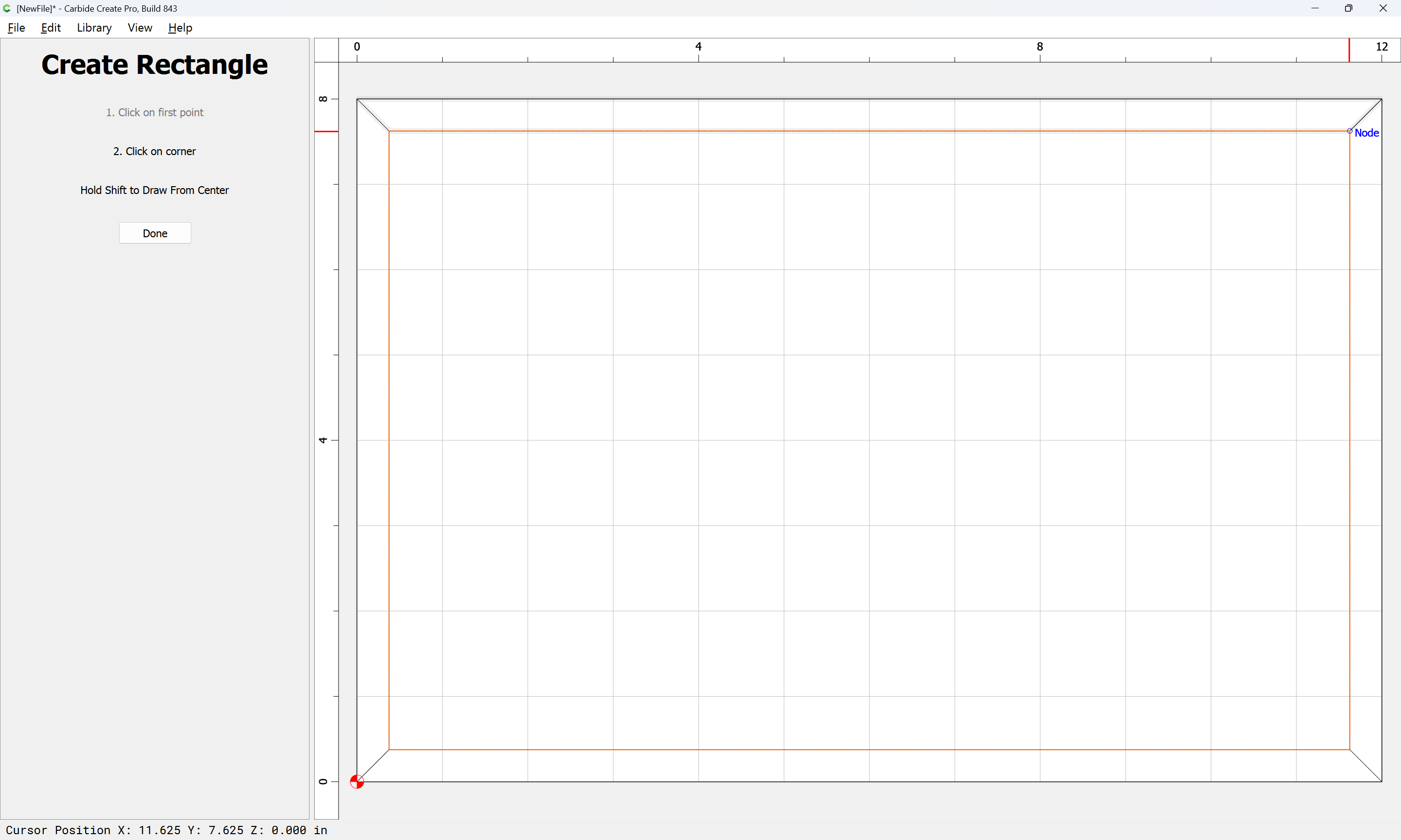
It is easiest to envision this by drawing rectangles which show this outline:
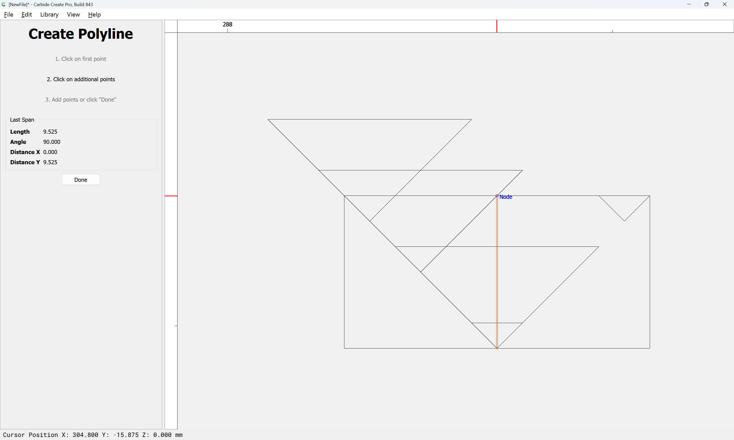
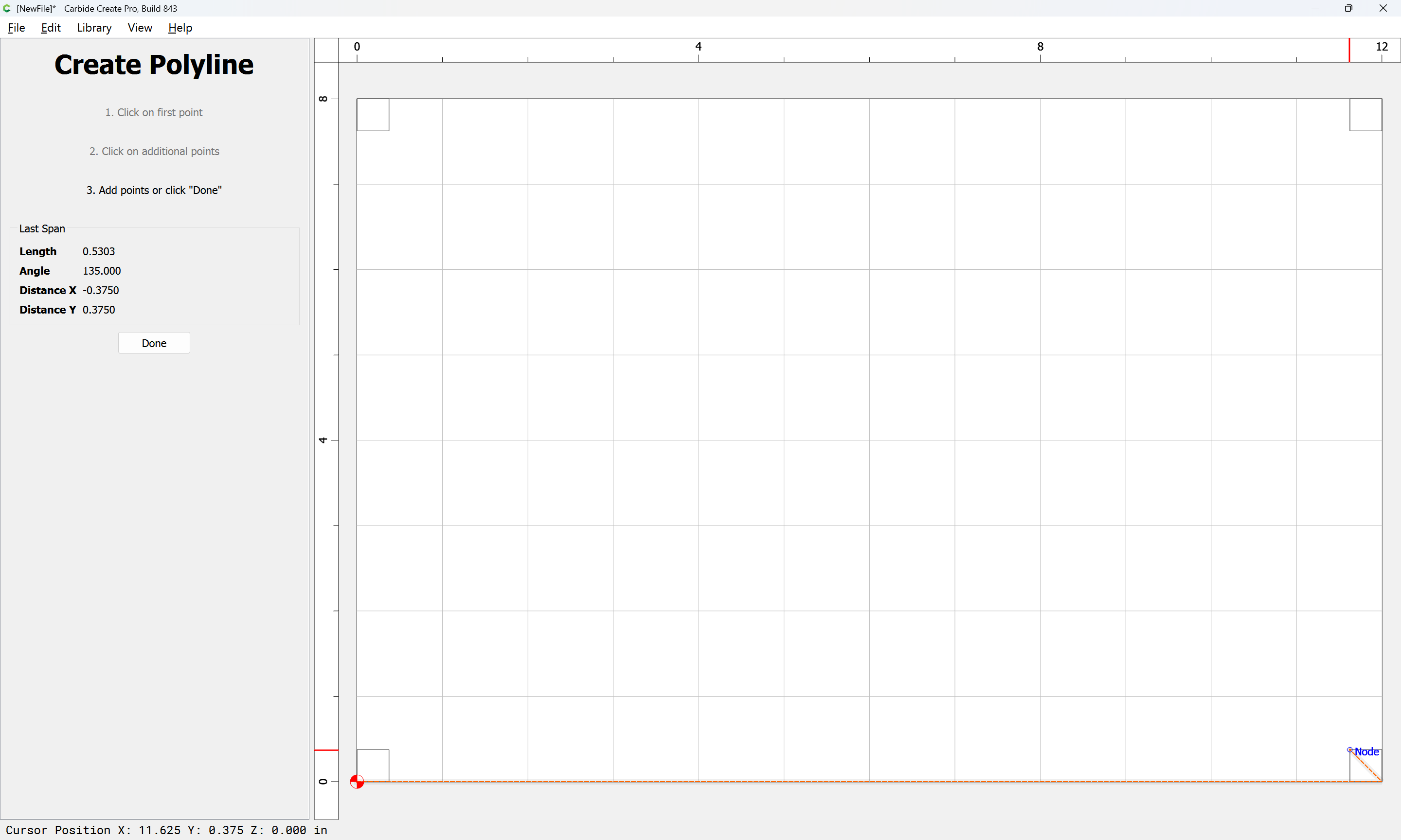
which may then have the requisite geometry for toolpaths drawn along their centers:

Done
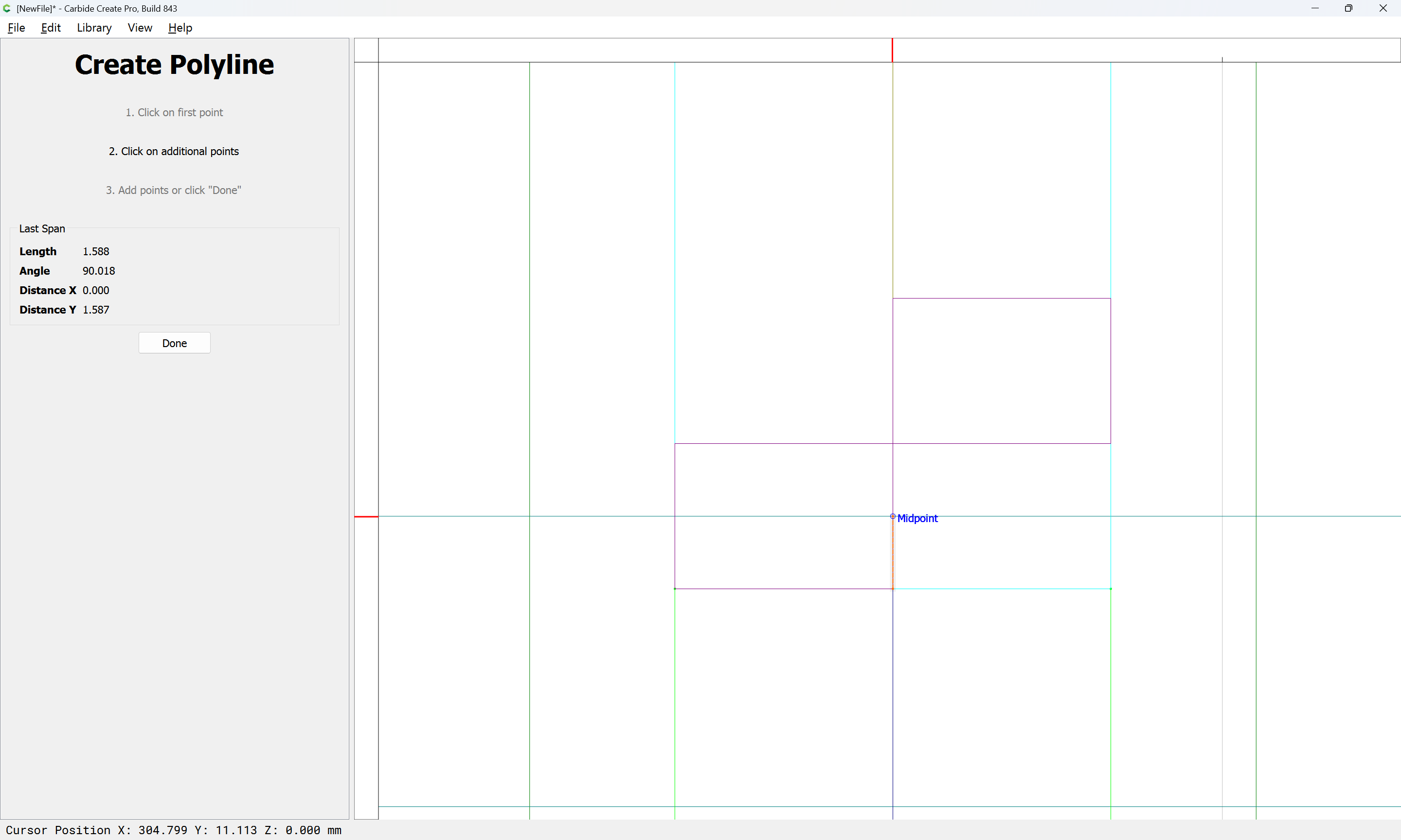
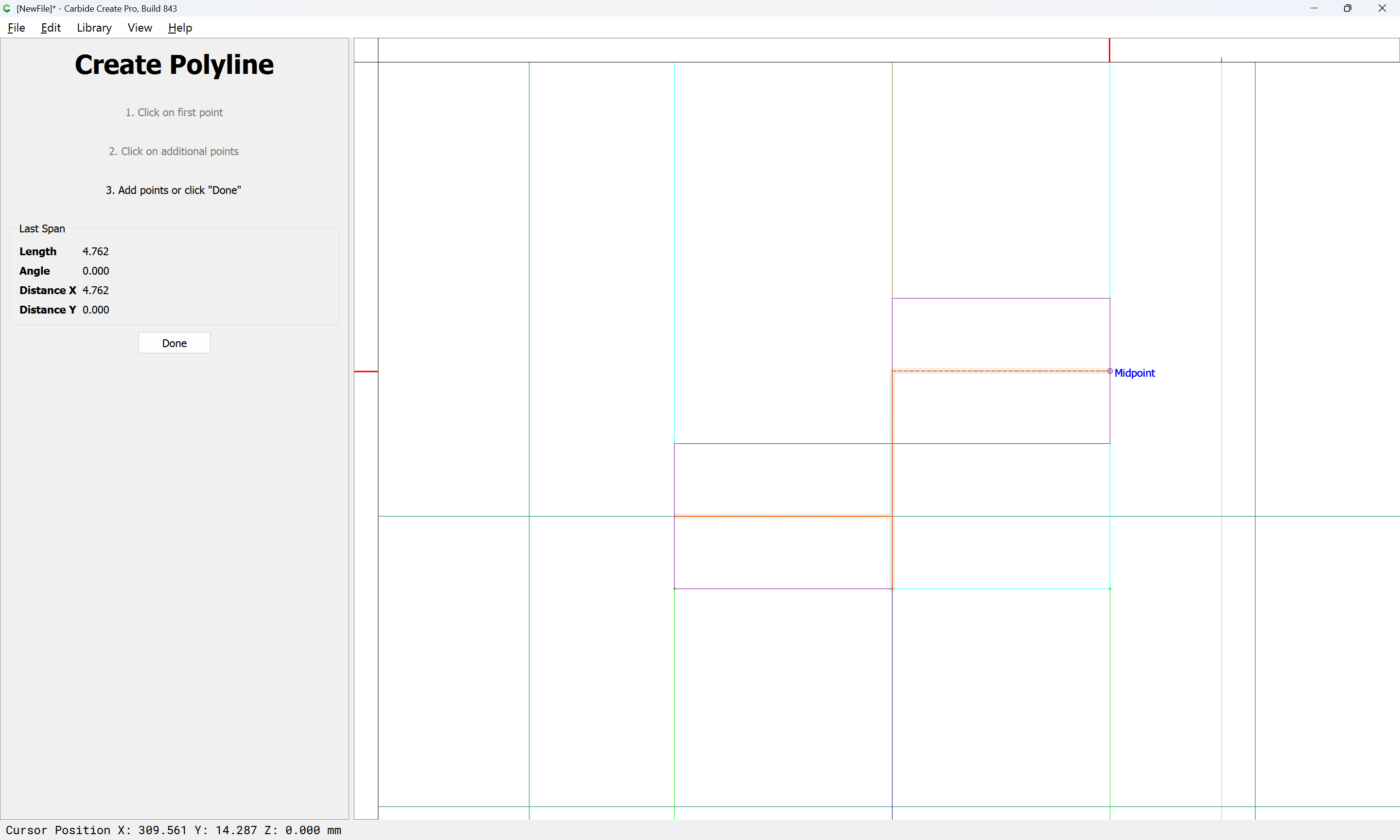
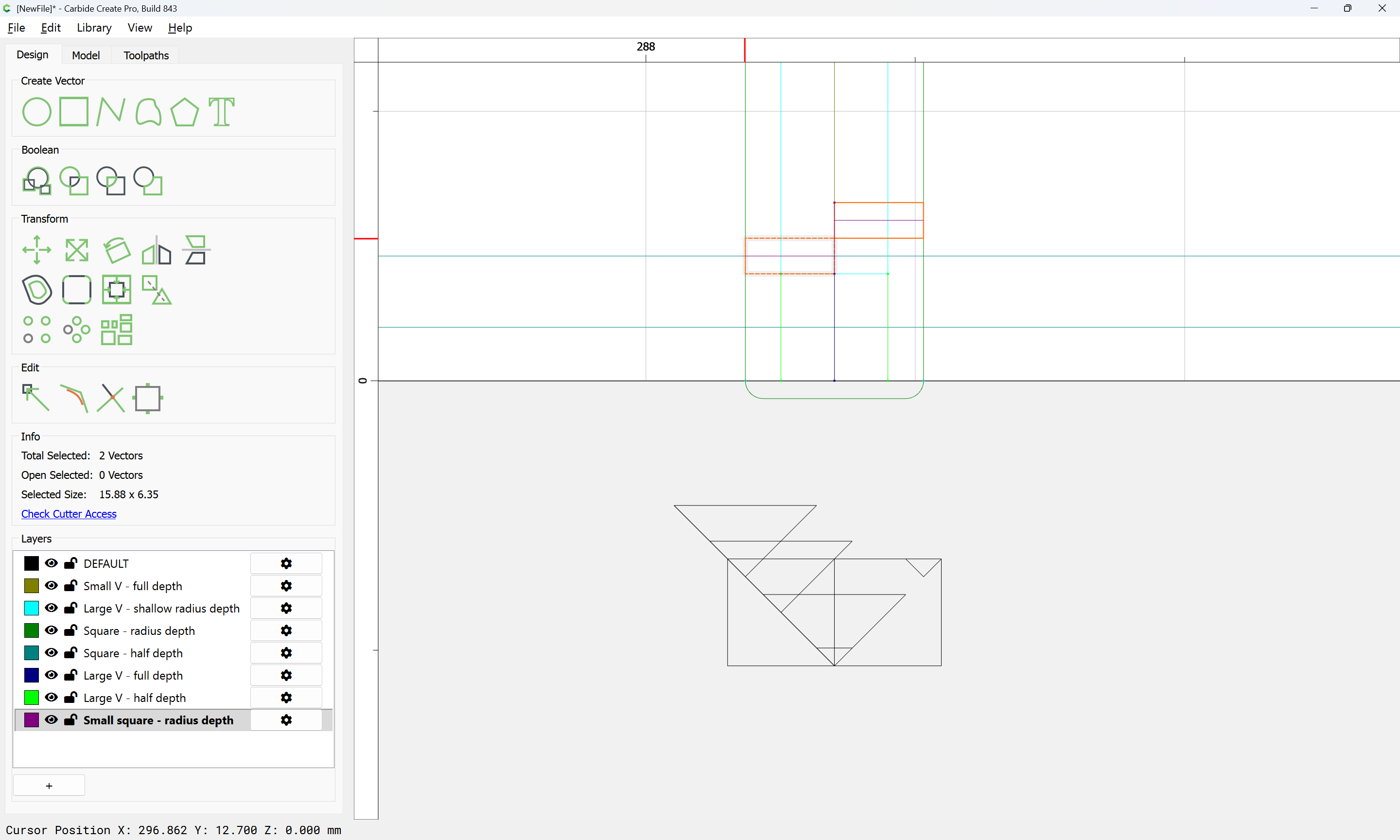
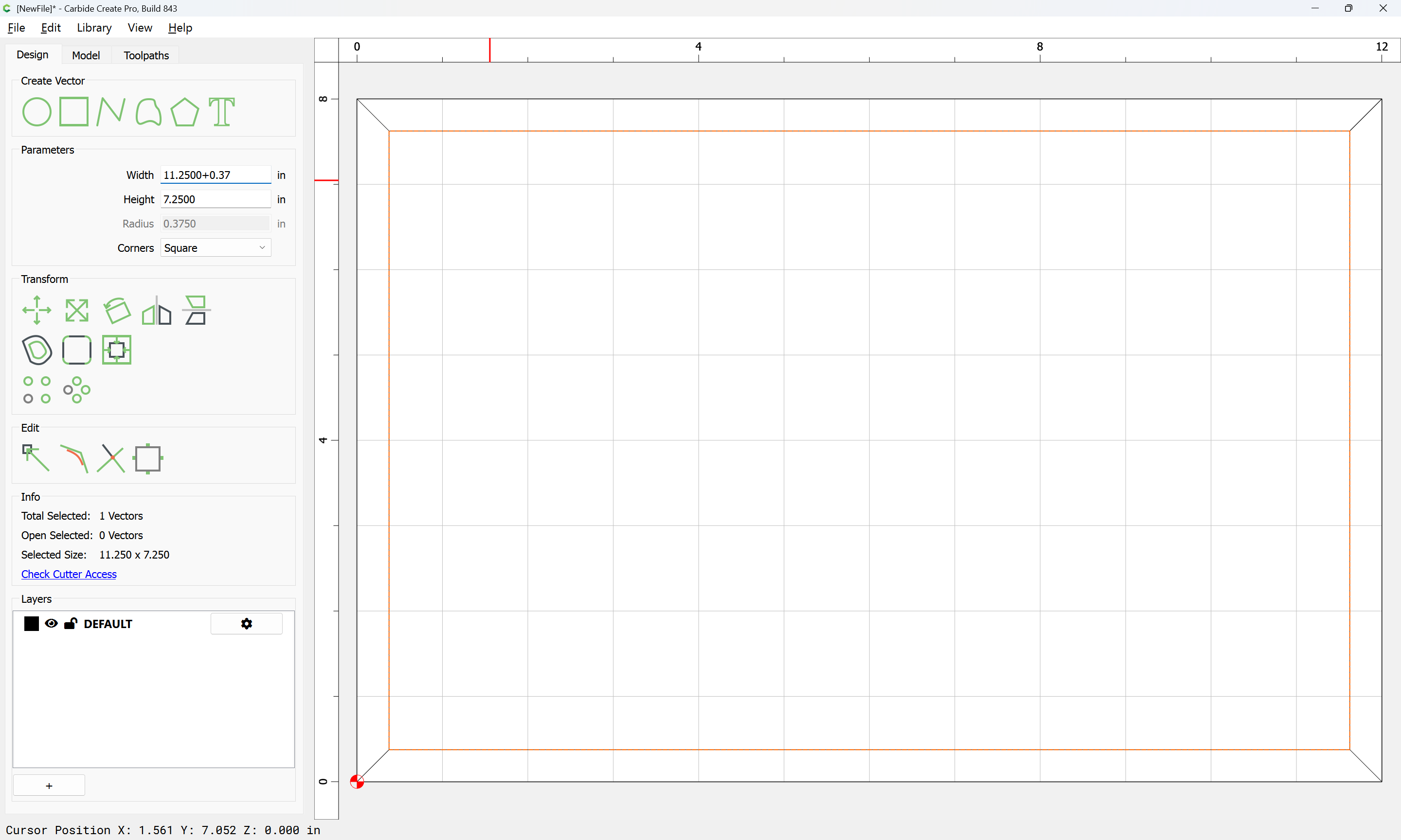
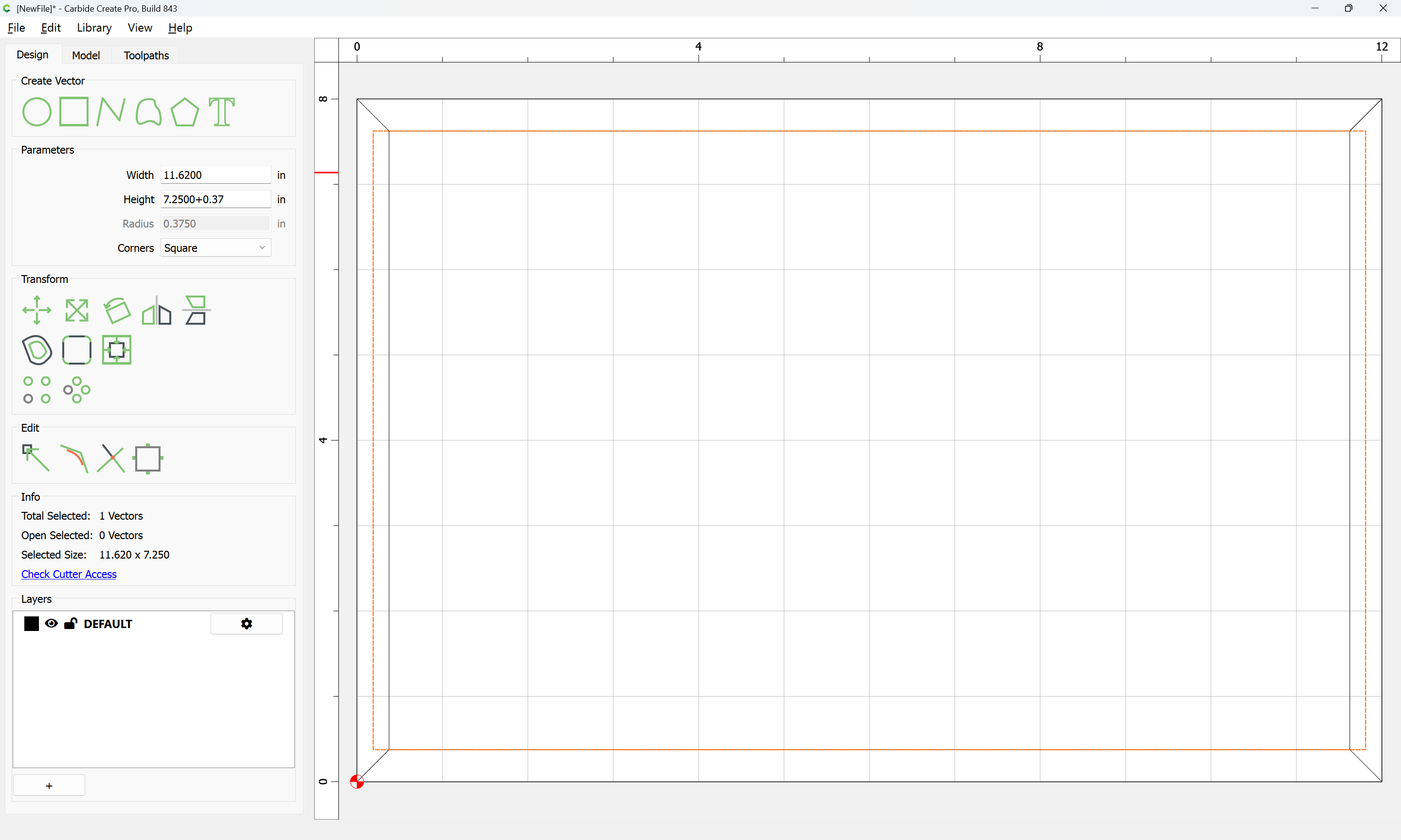
Except that they need to be slightly adjusted in dimension across the joint — they need to be as wide as:
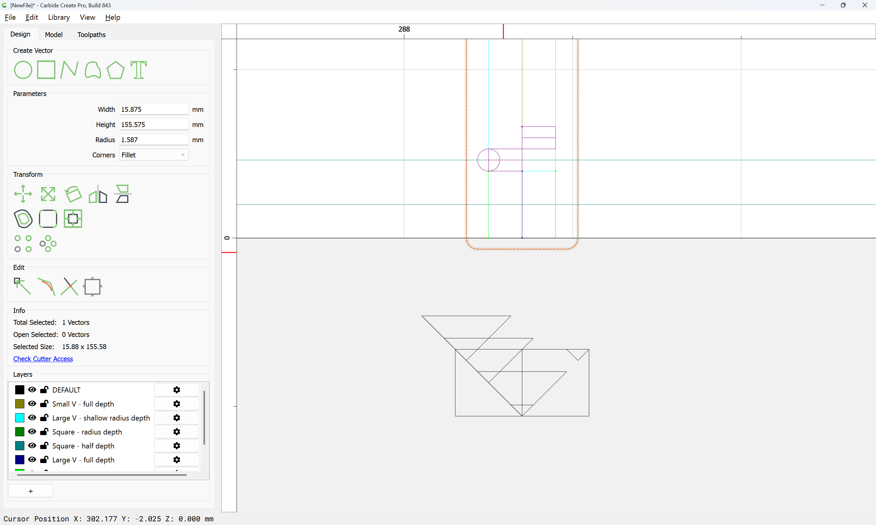

Done
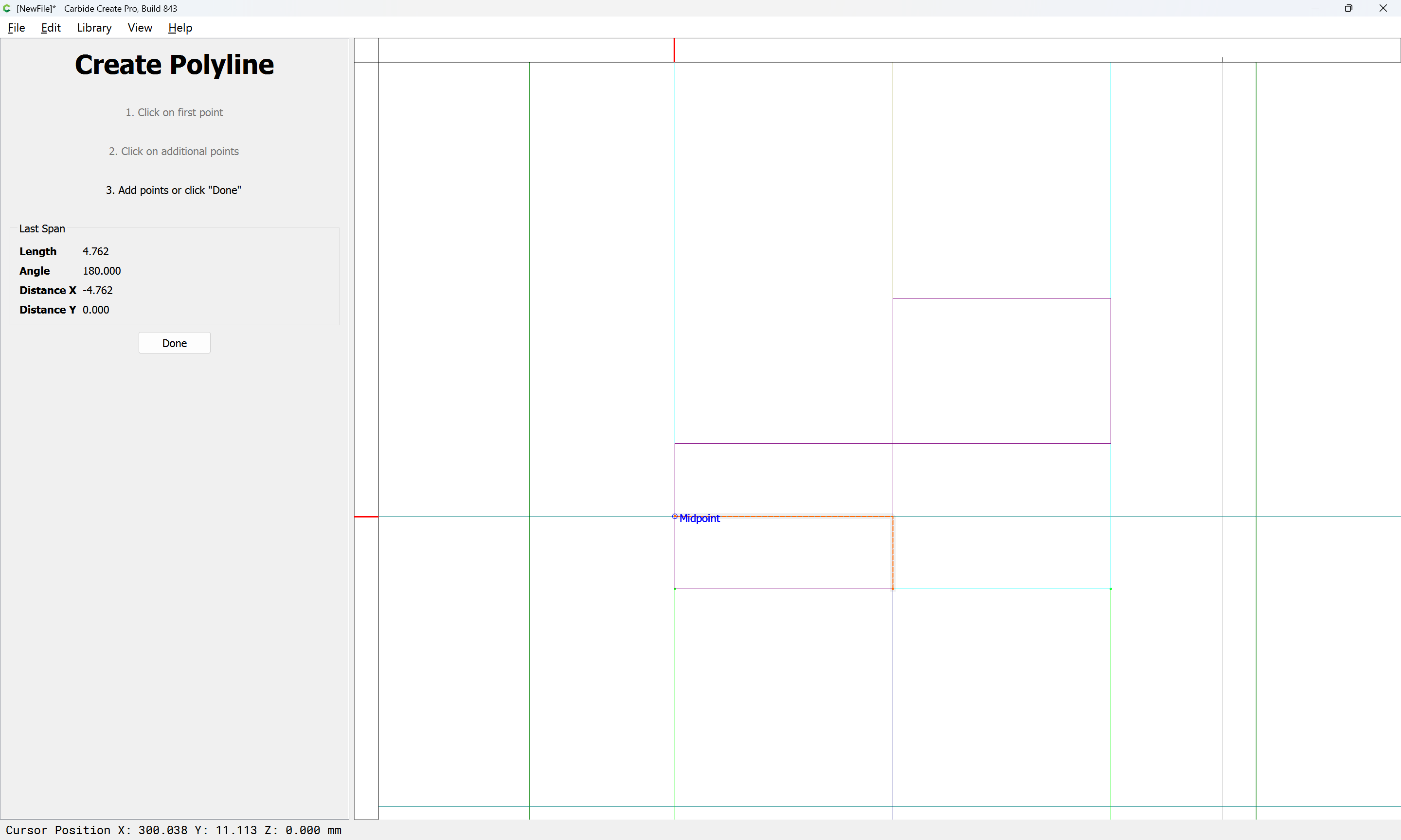
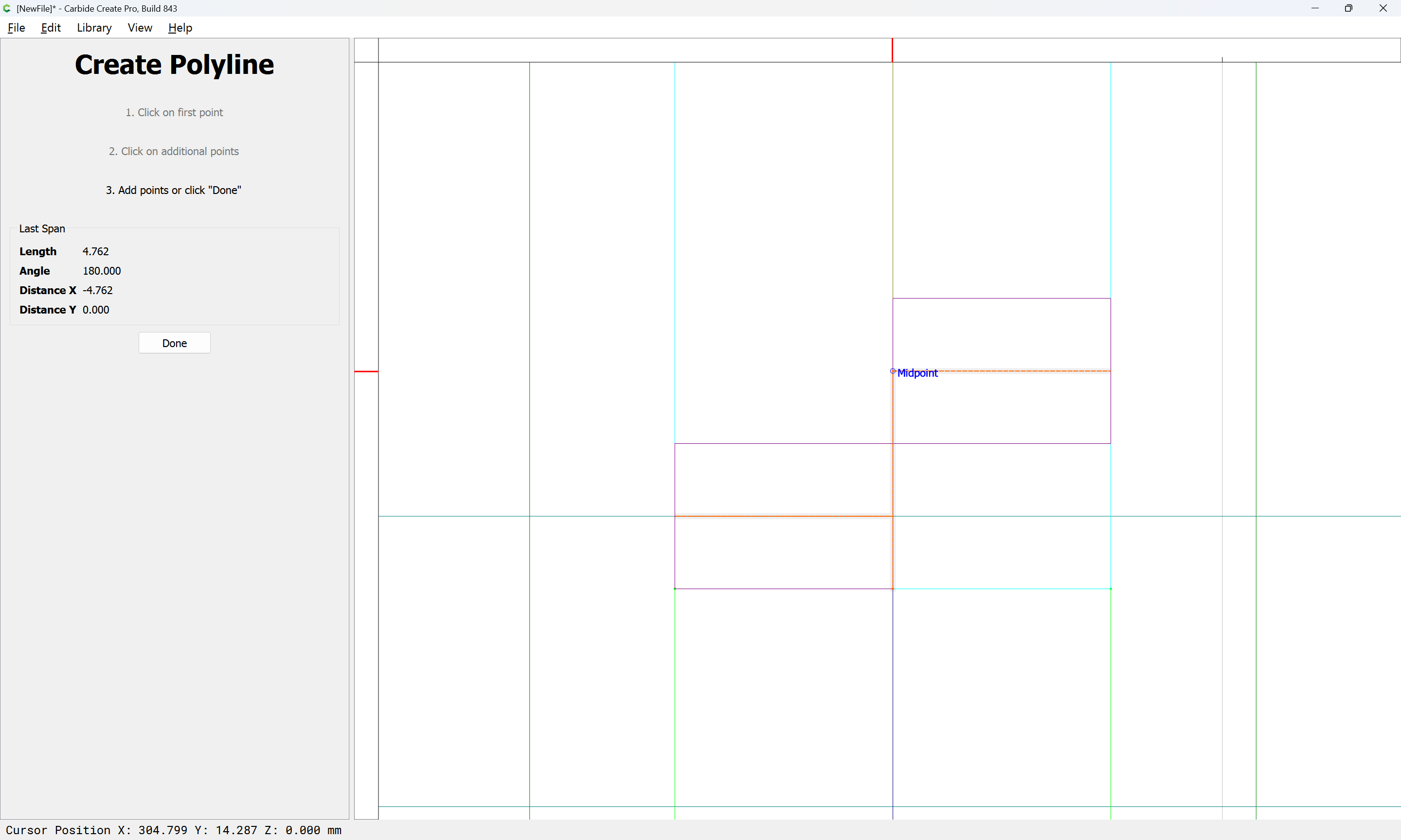
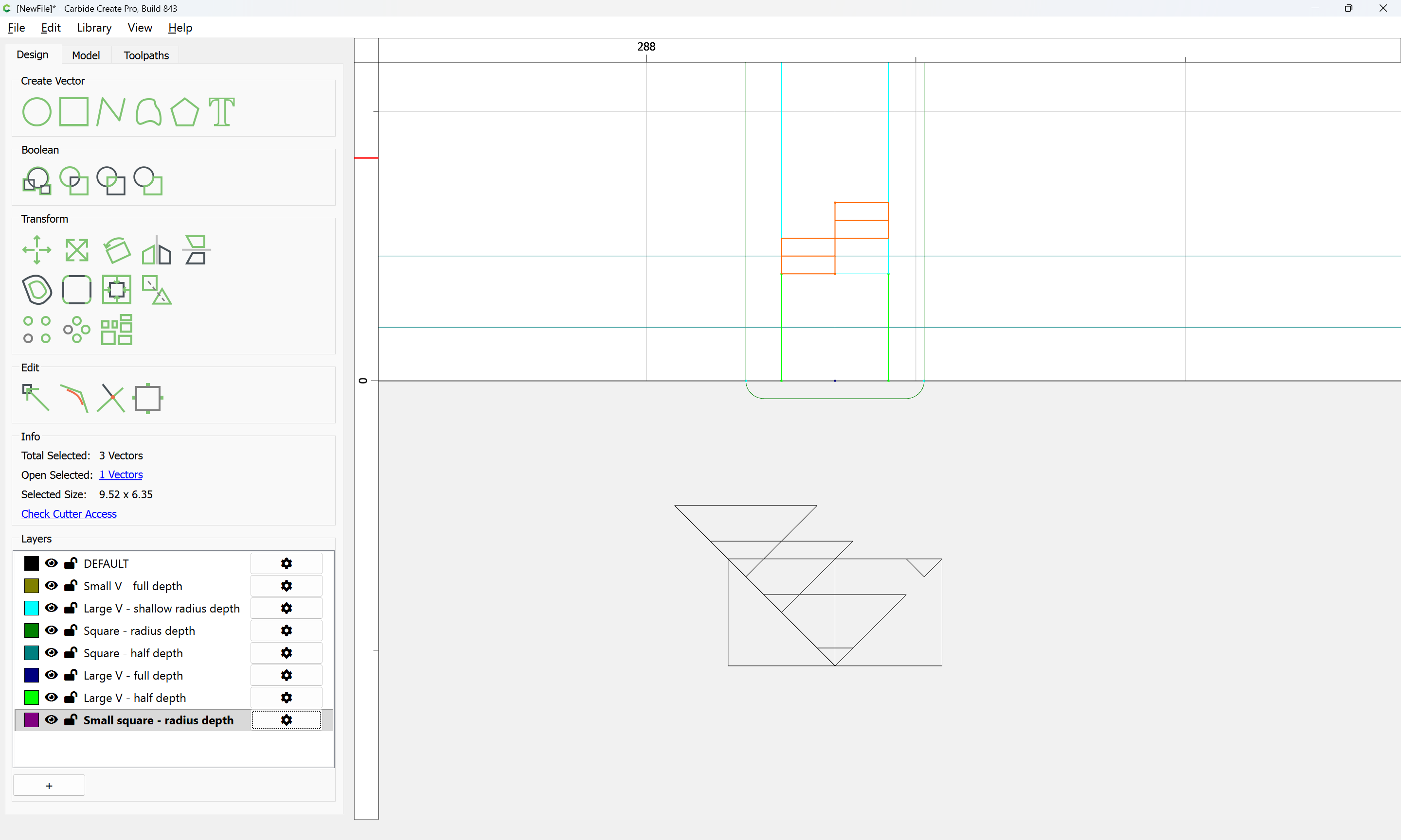
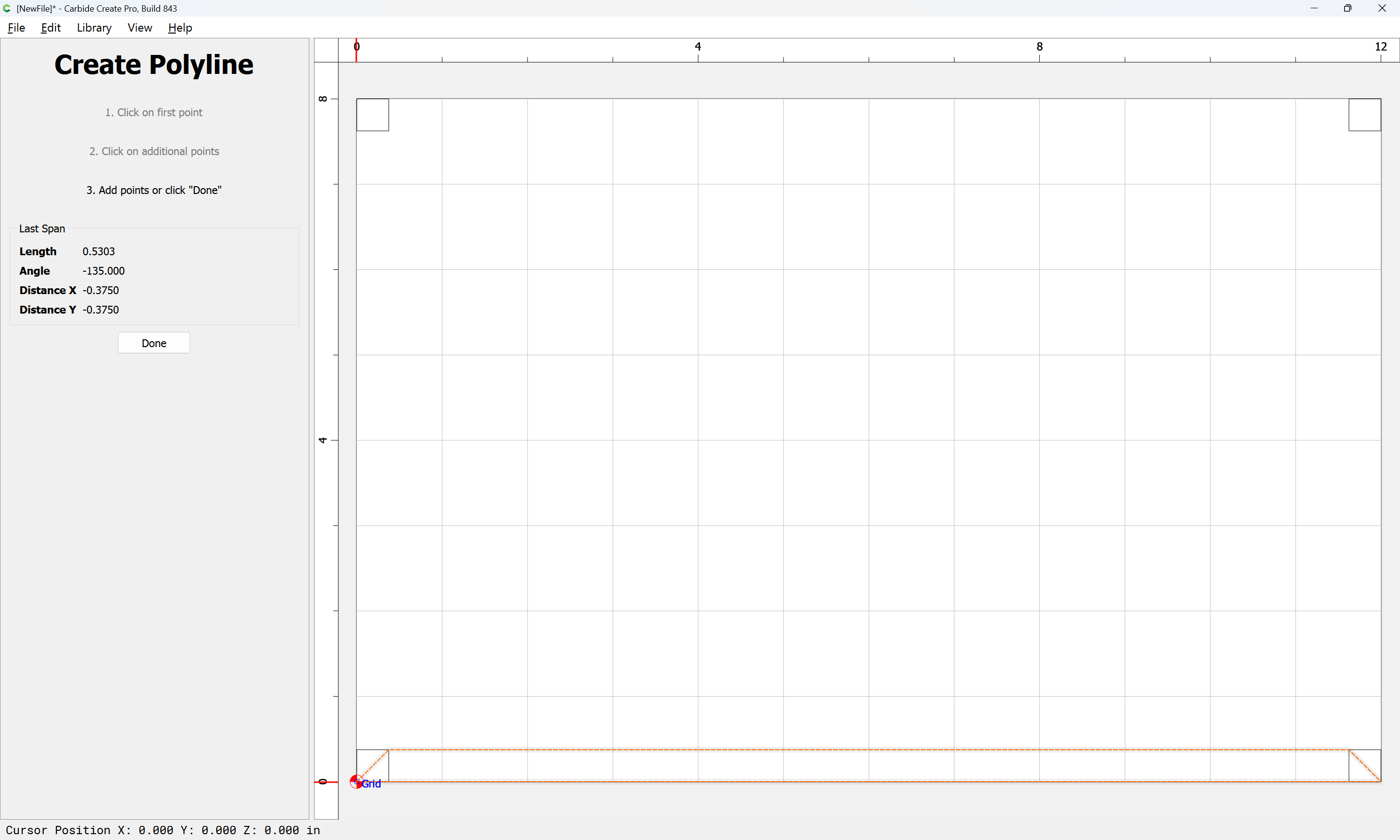
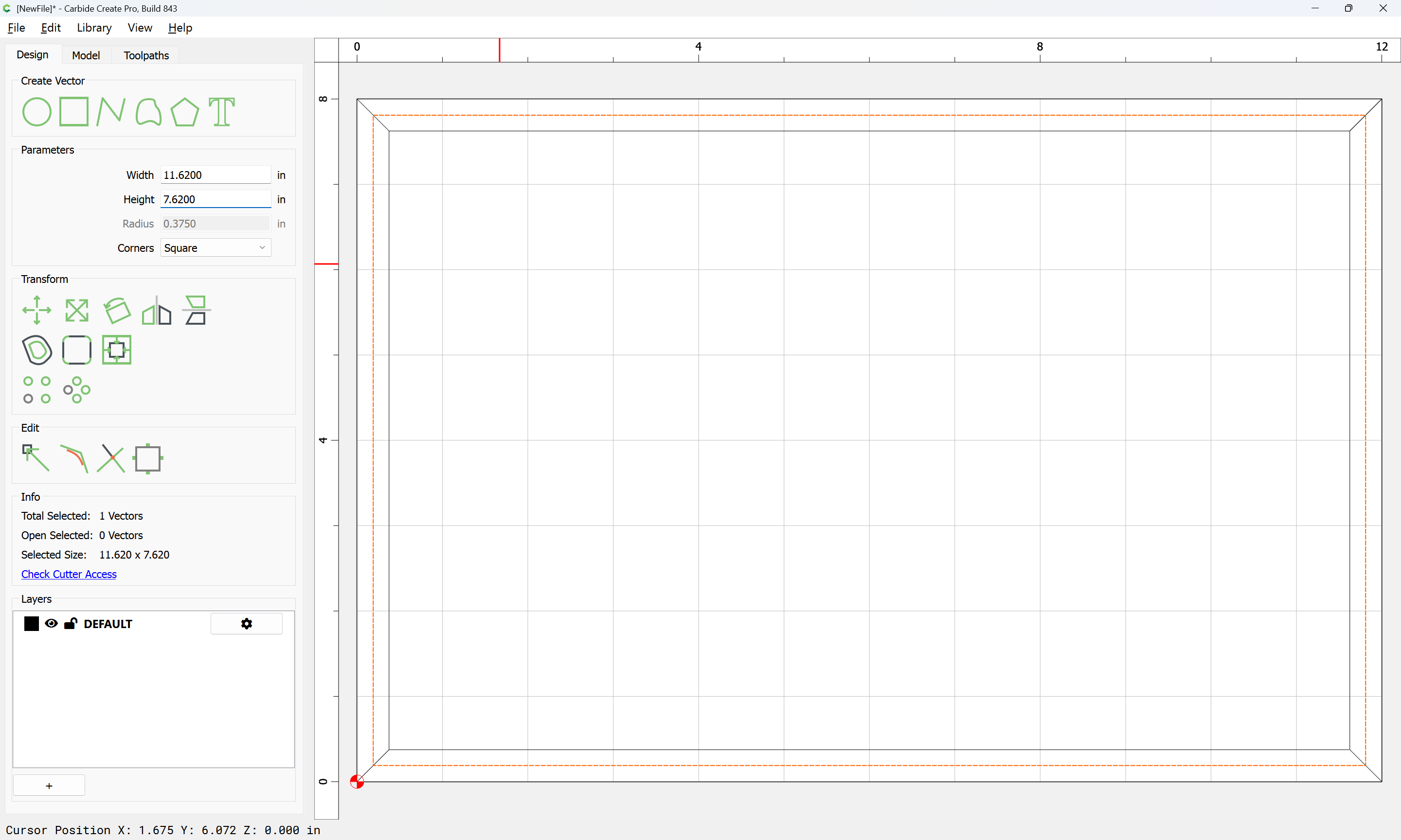
Then the rectangles may be deleted:
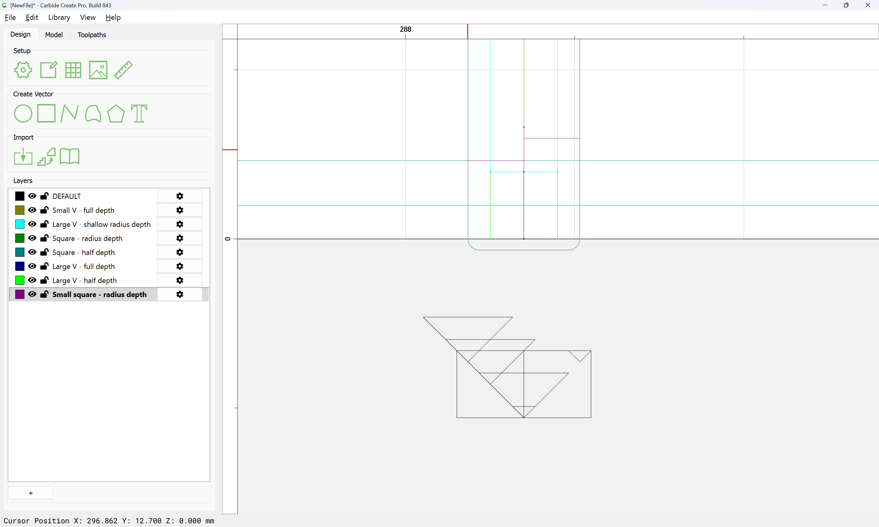
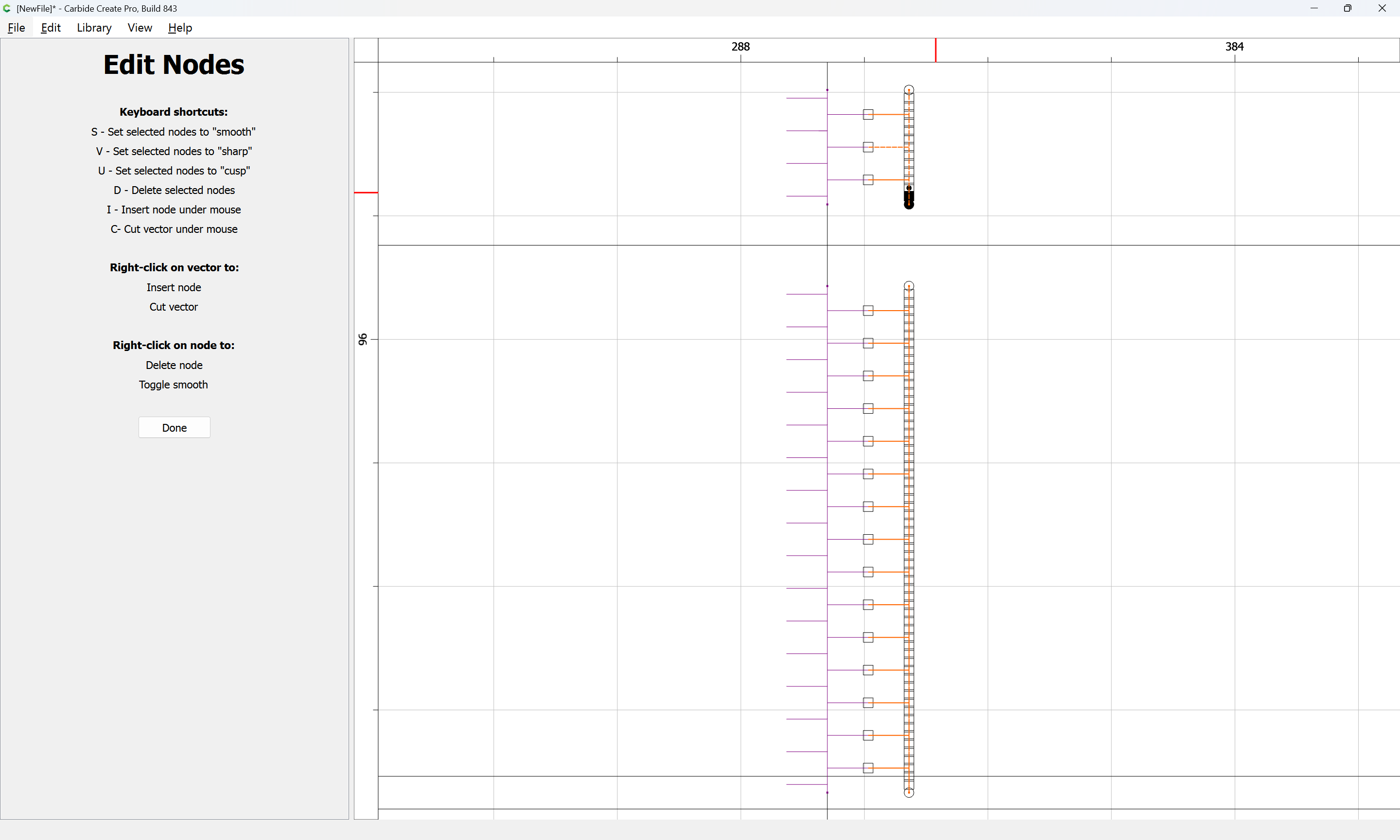
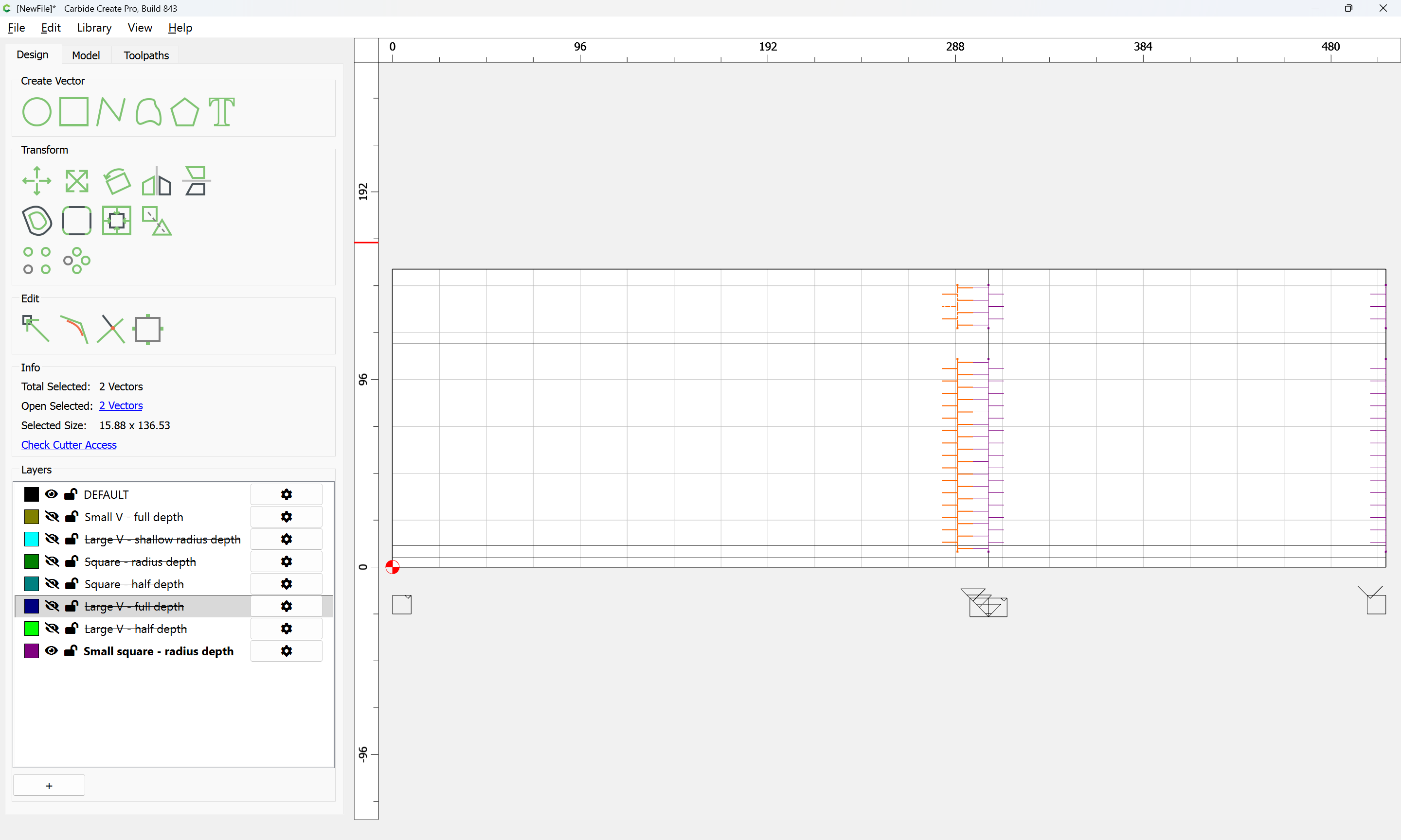
and the toolpath geometry duplicated as needed using a Linear Array:
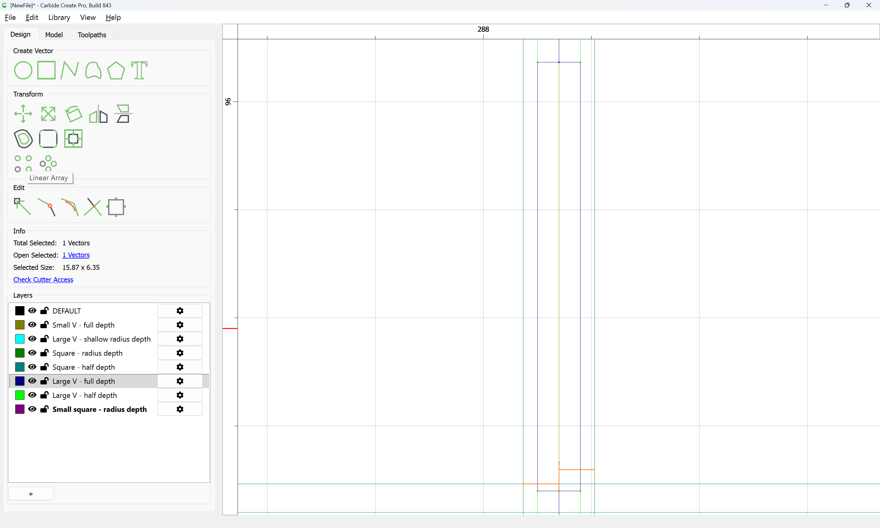
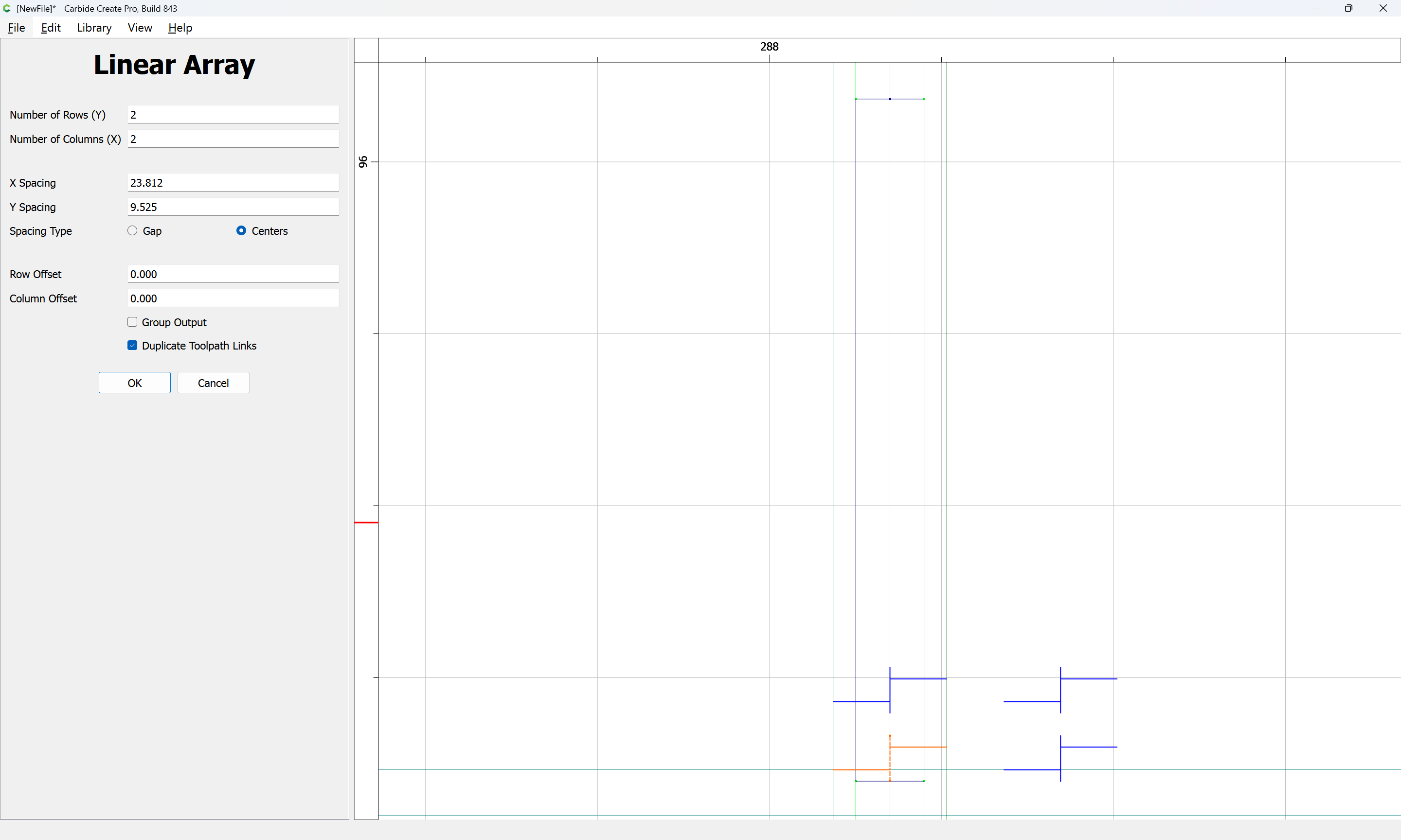
adjusting so as to fill the desired region:
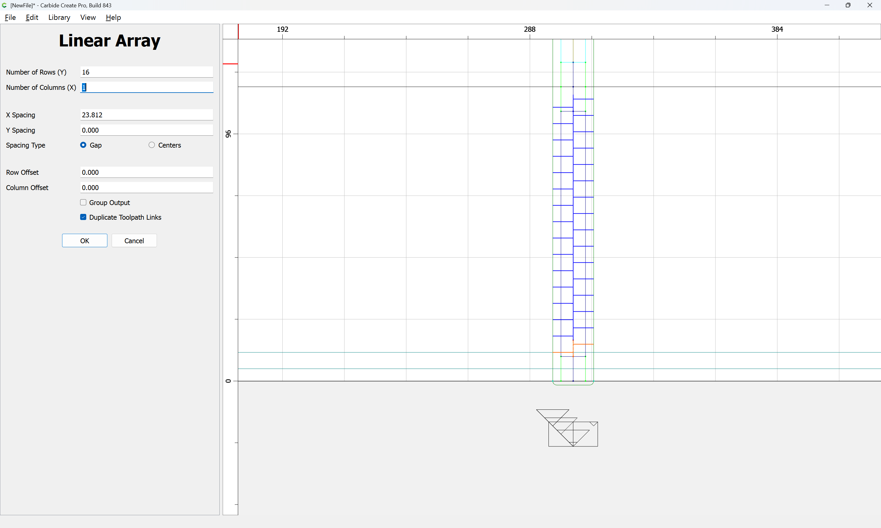
OK
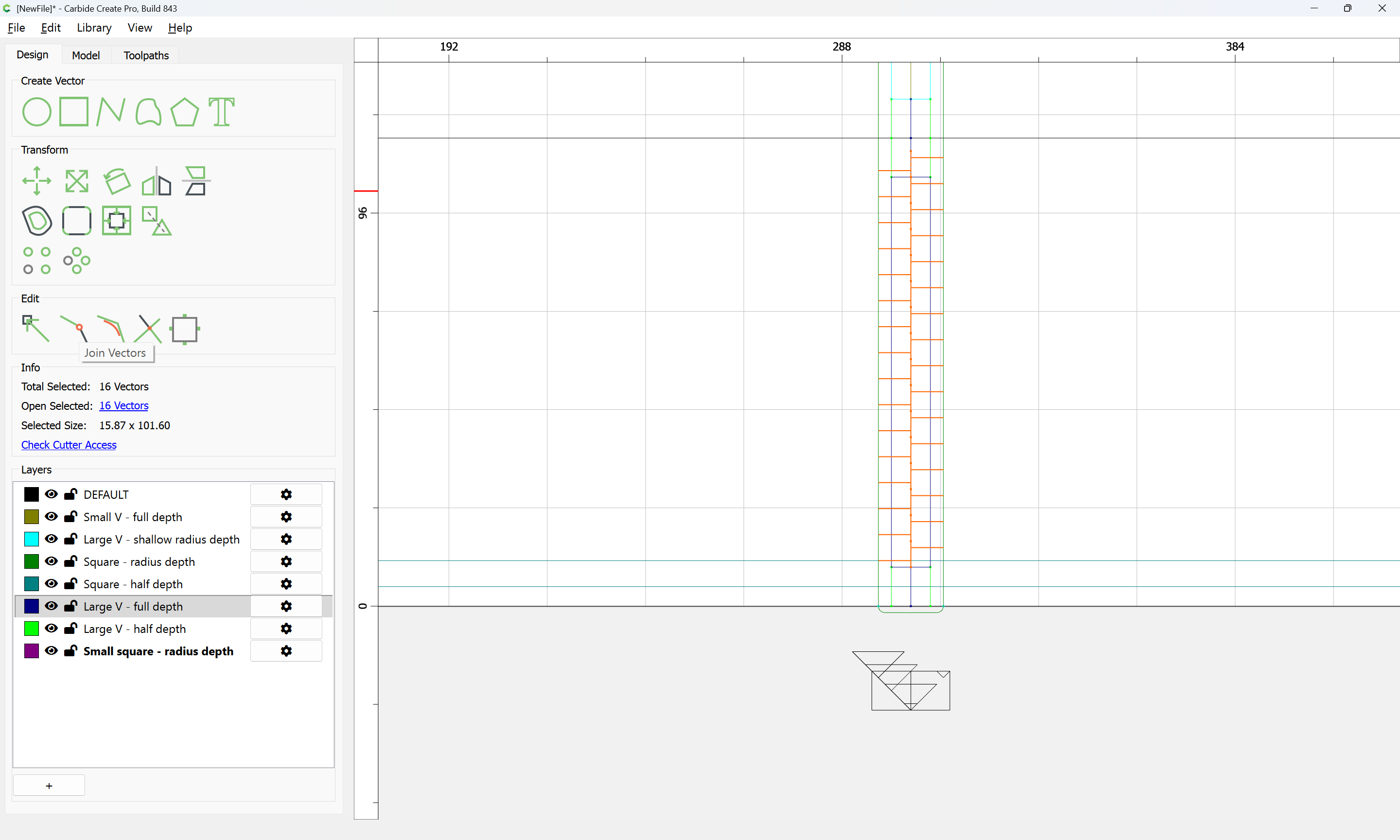
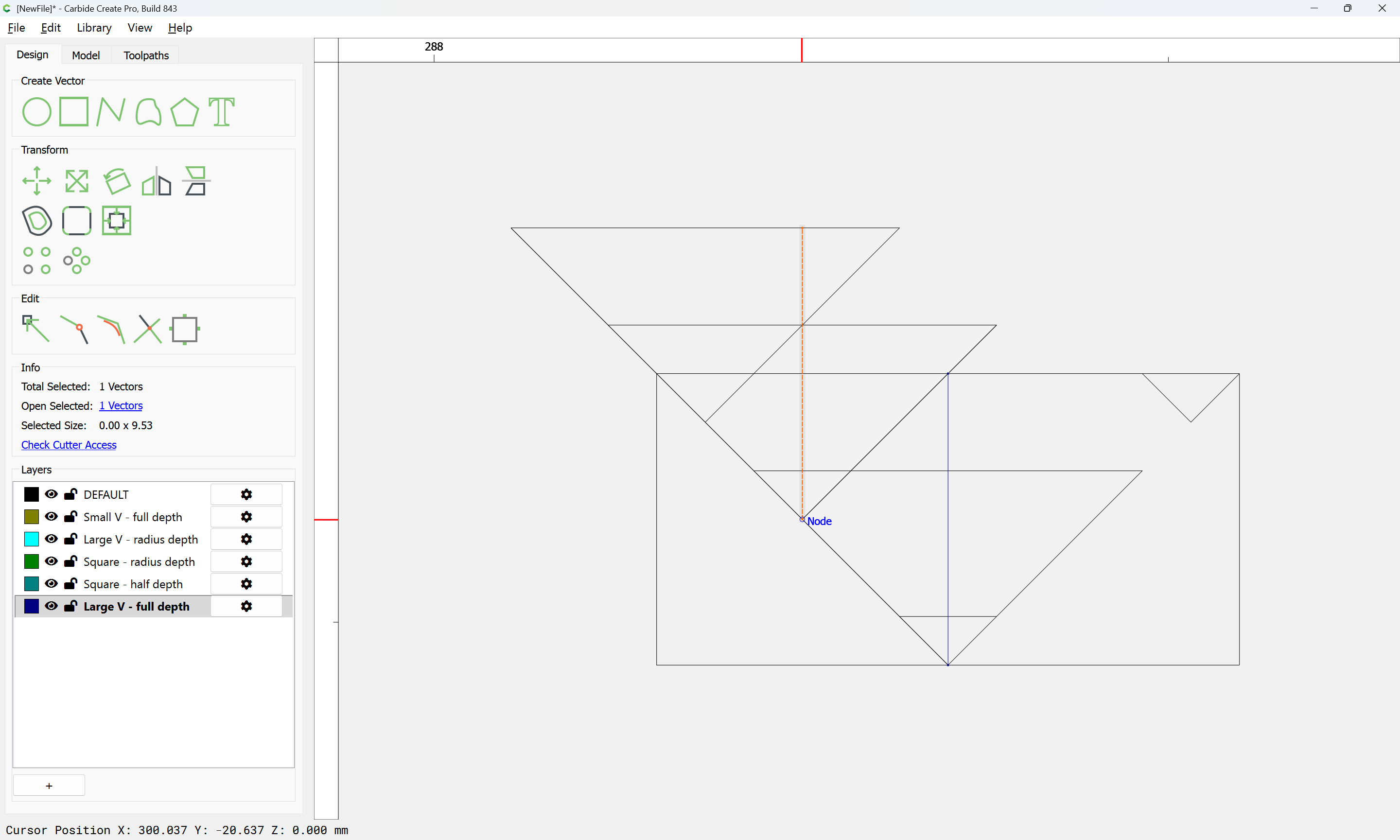
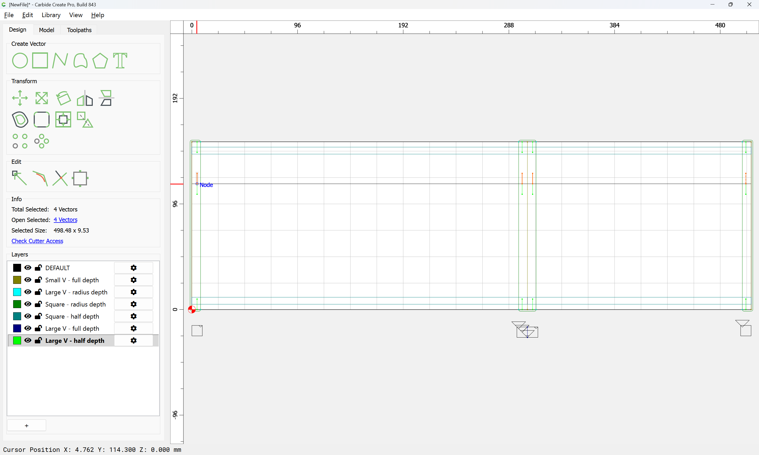
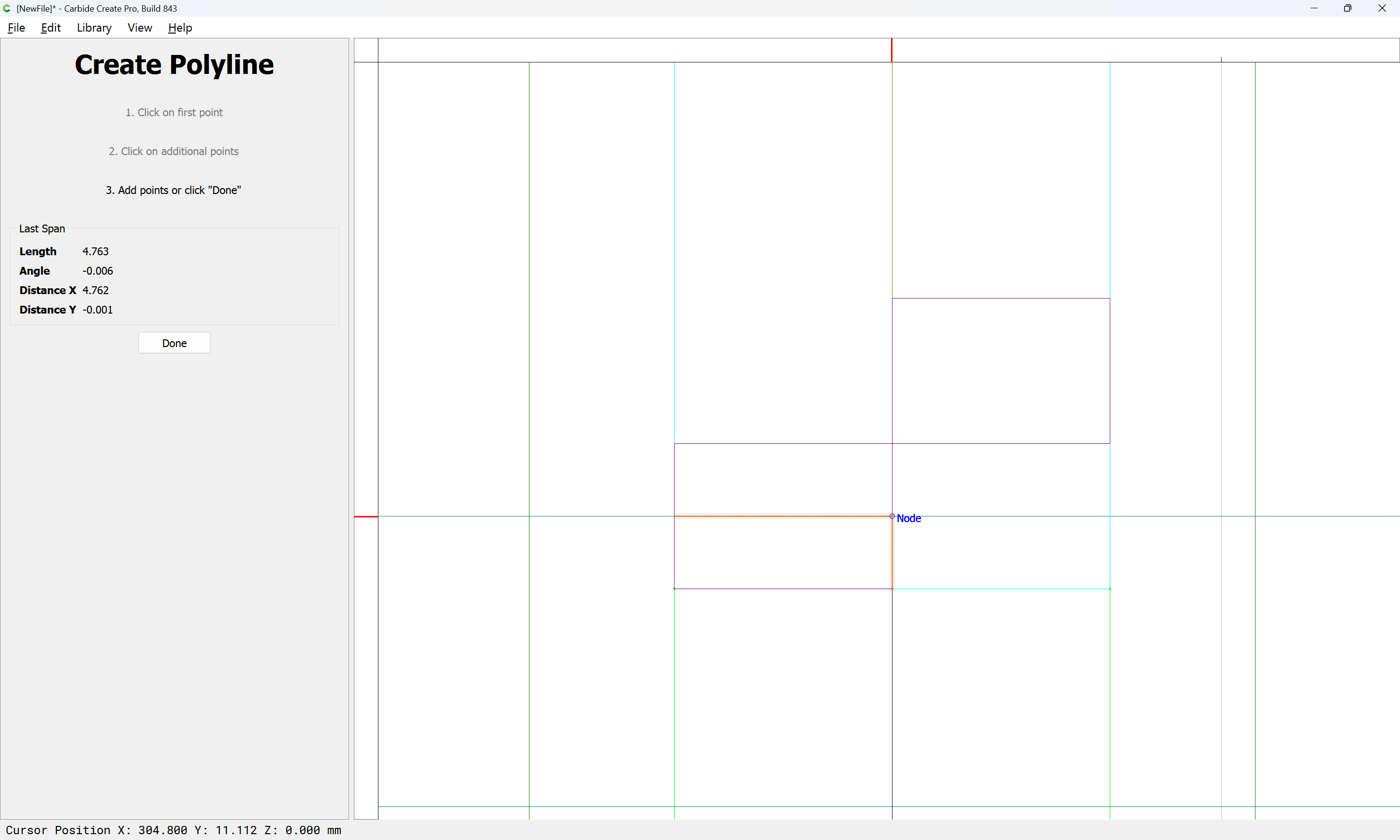
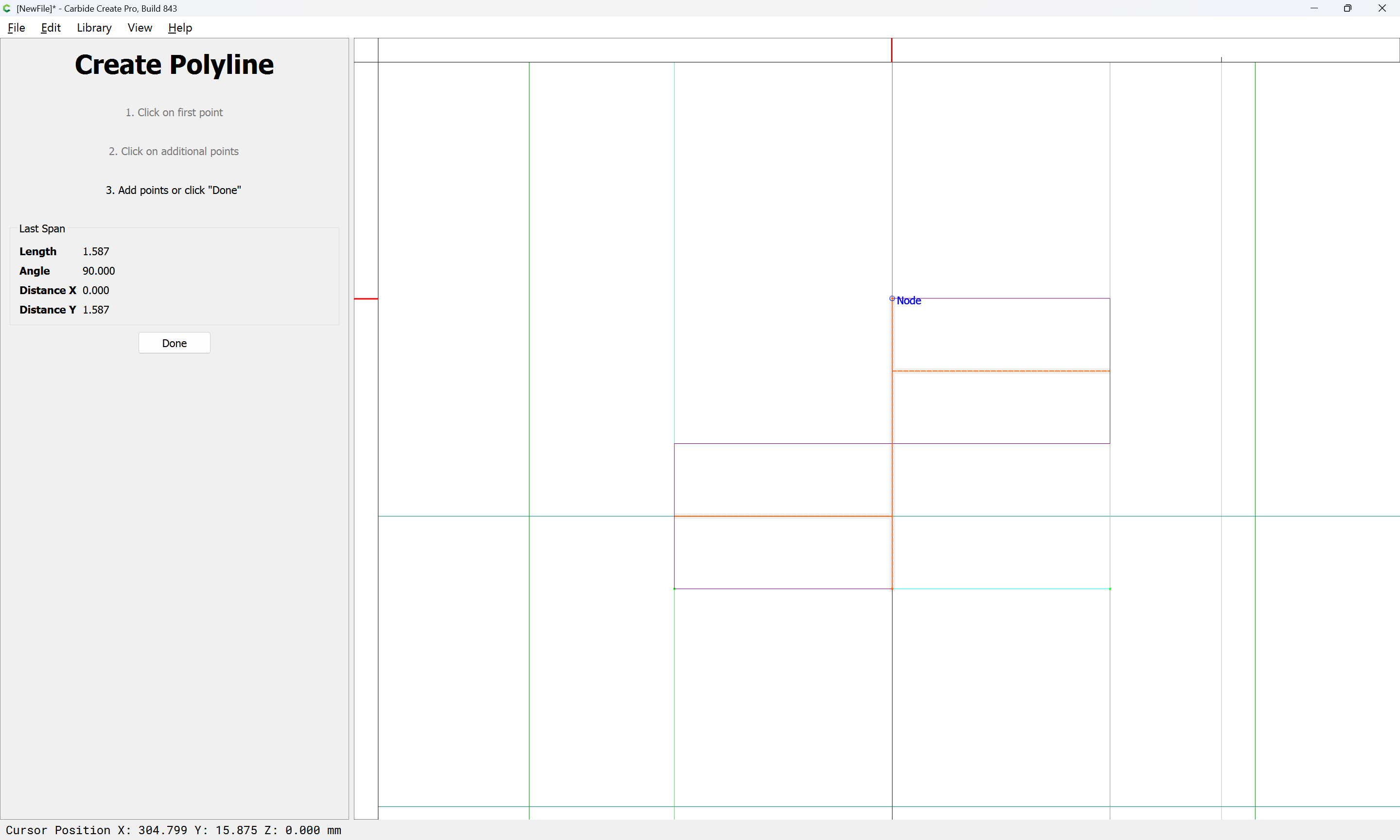
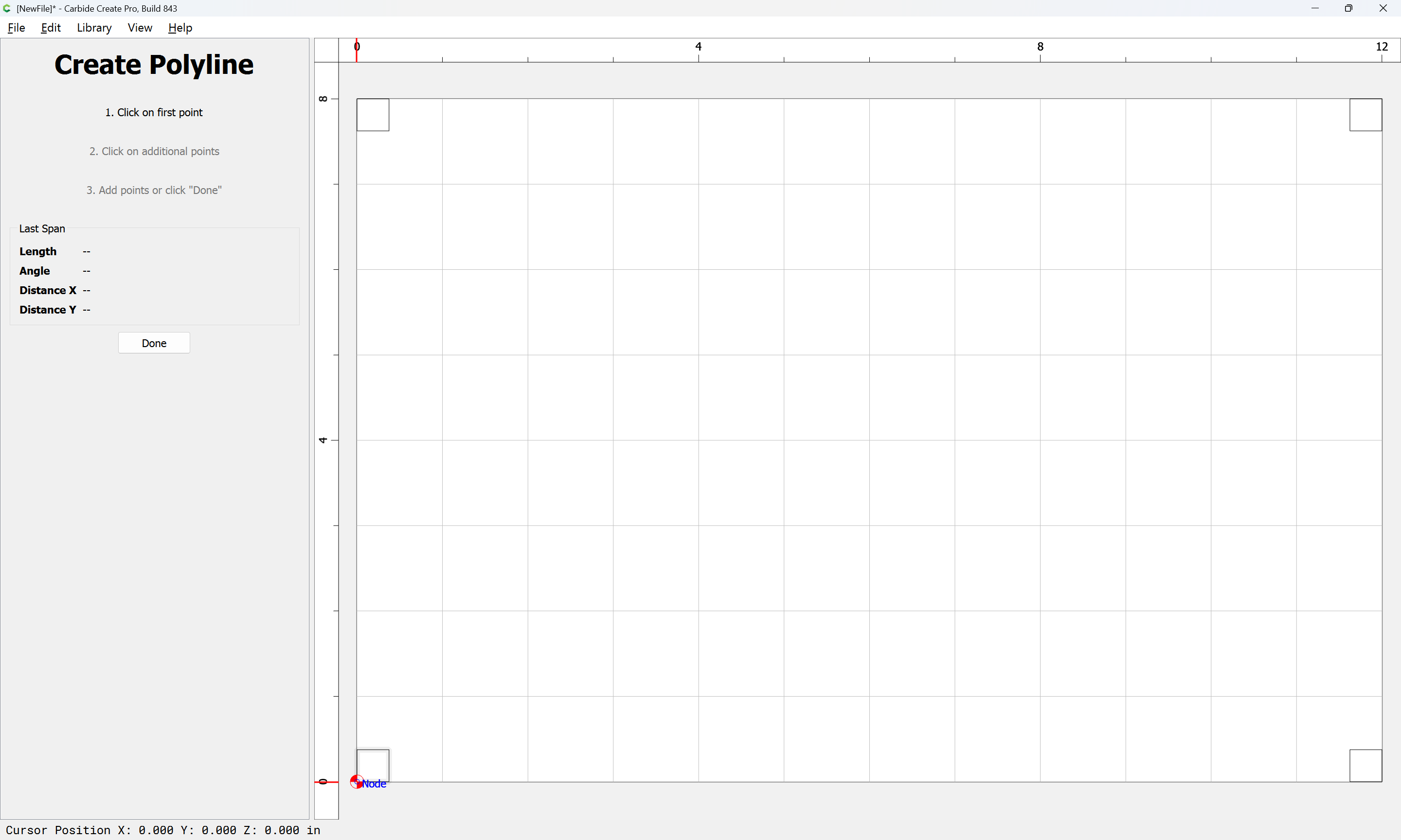
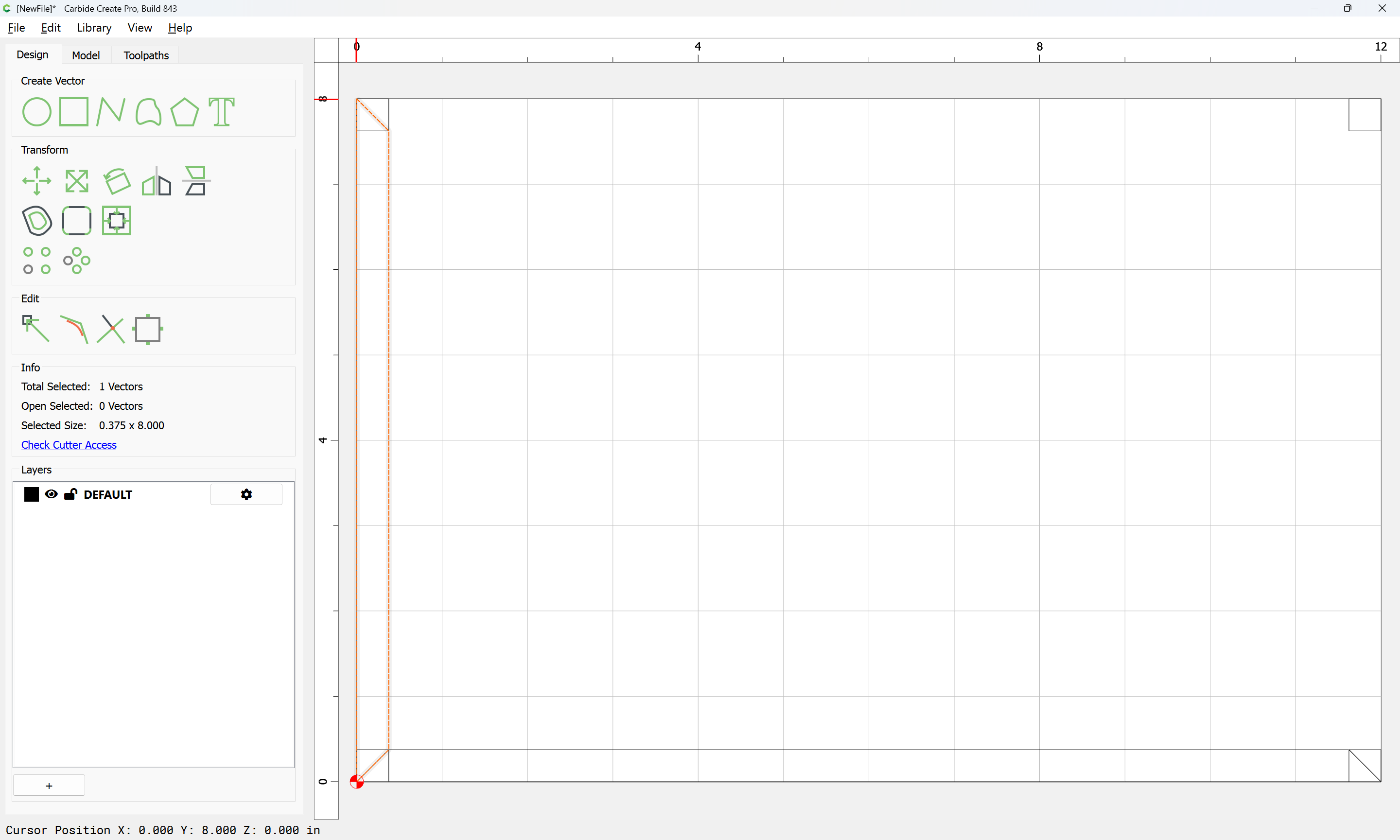
The geometry may then be joined:
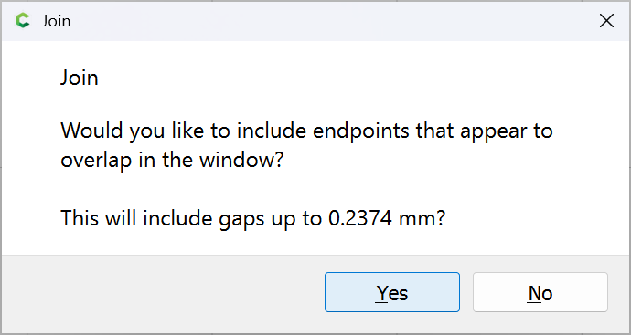
Yes
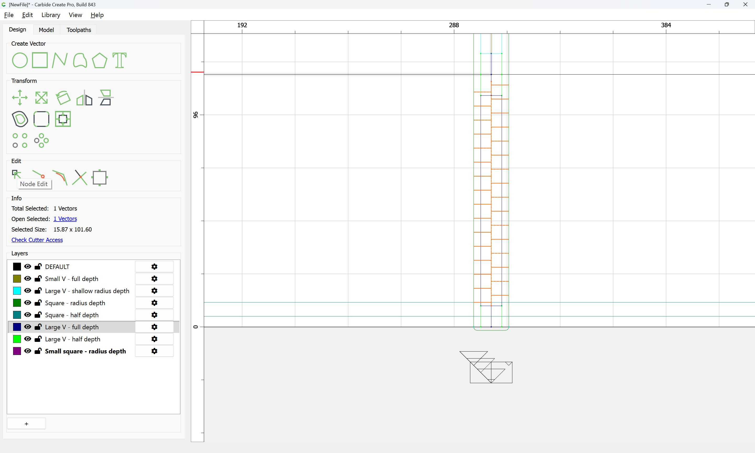
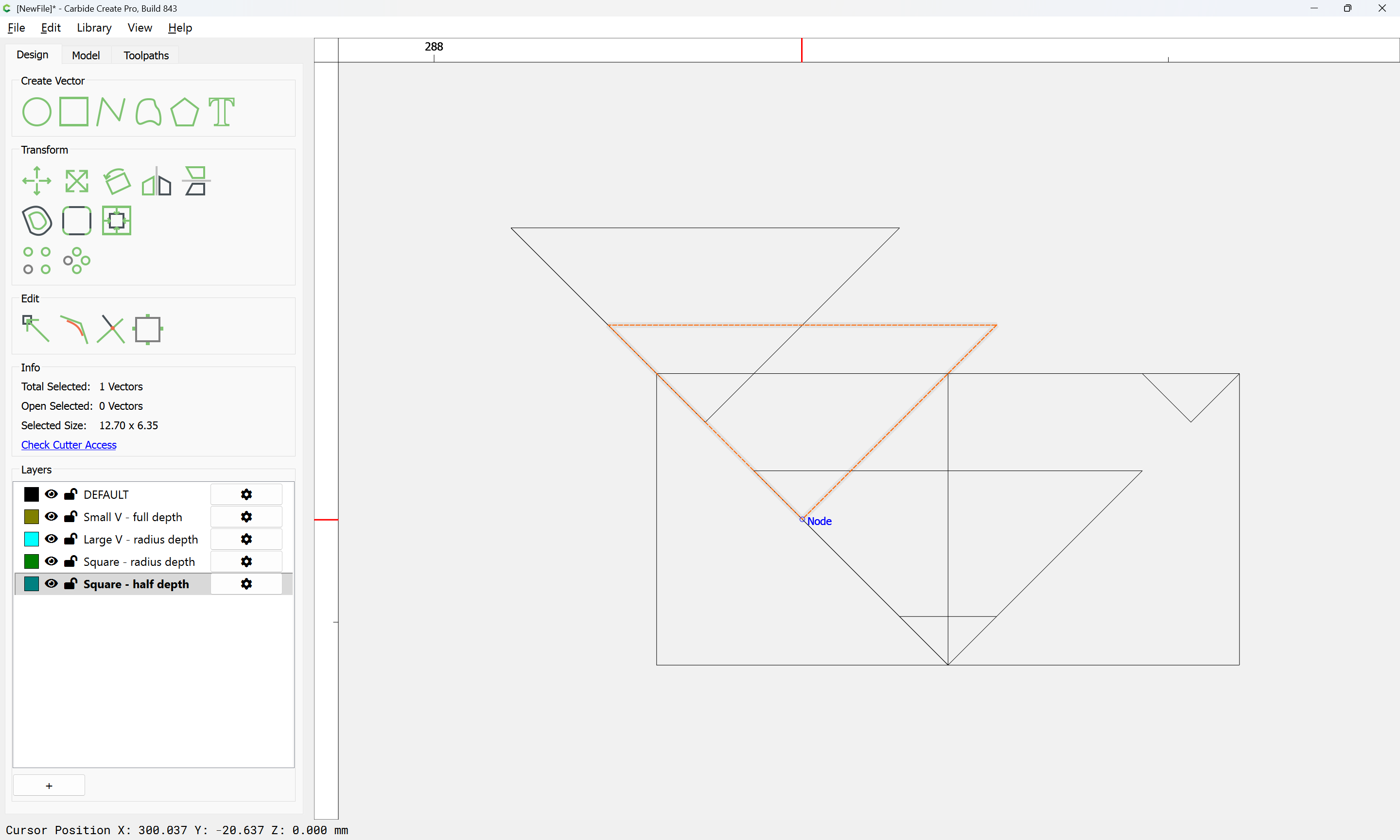
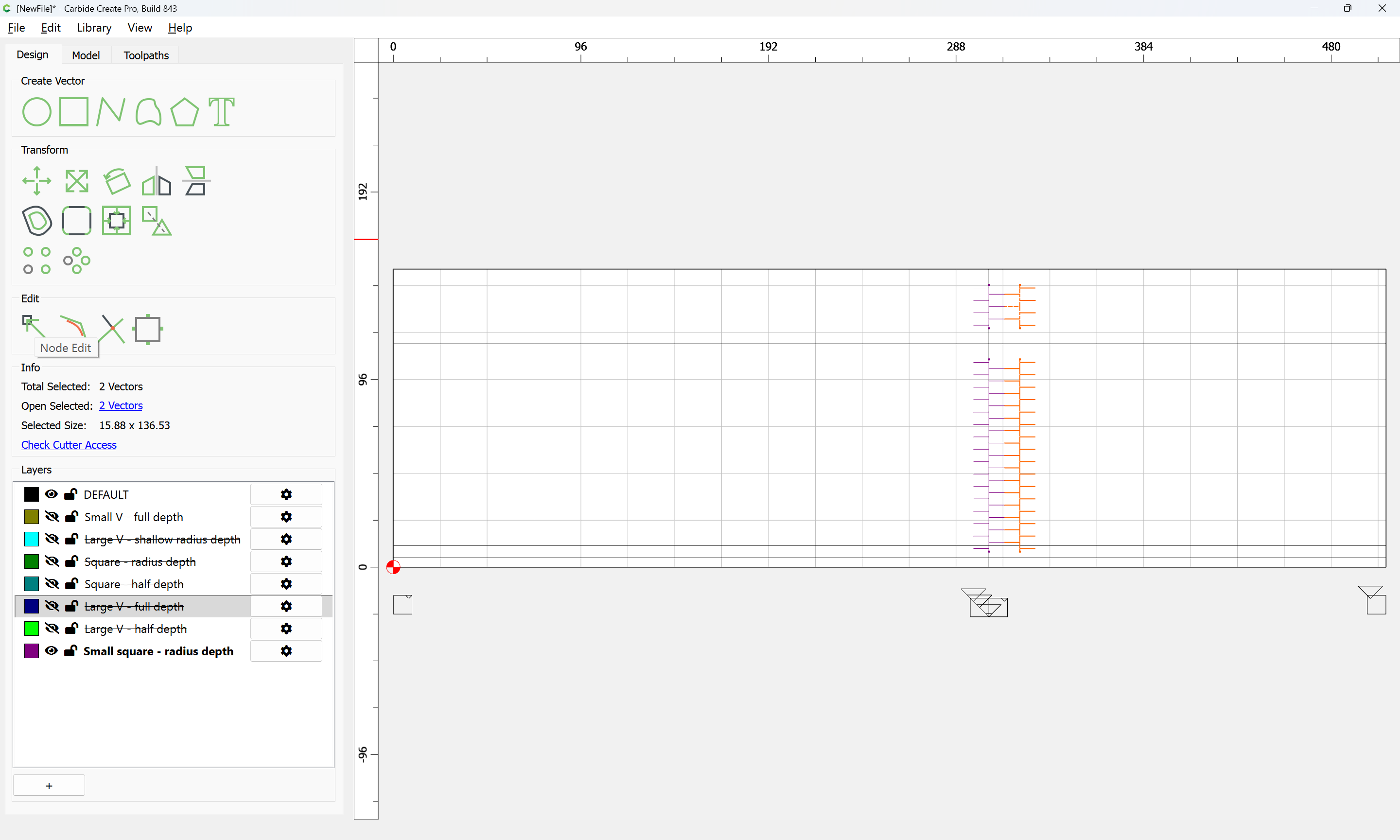
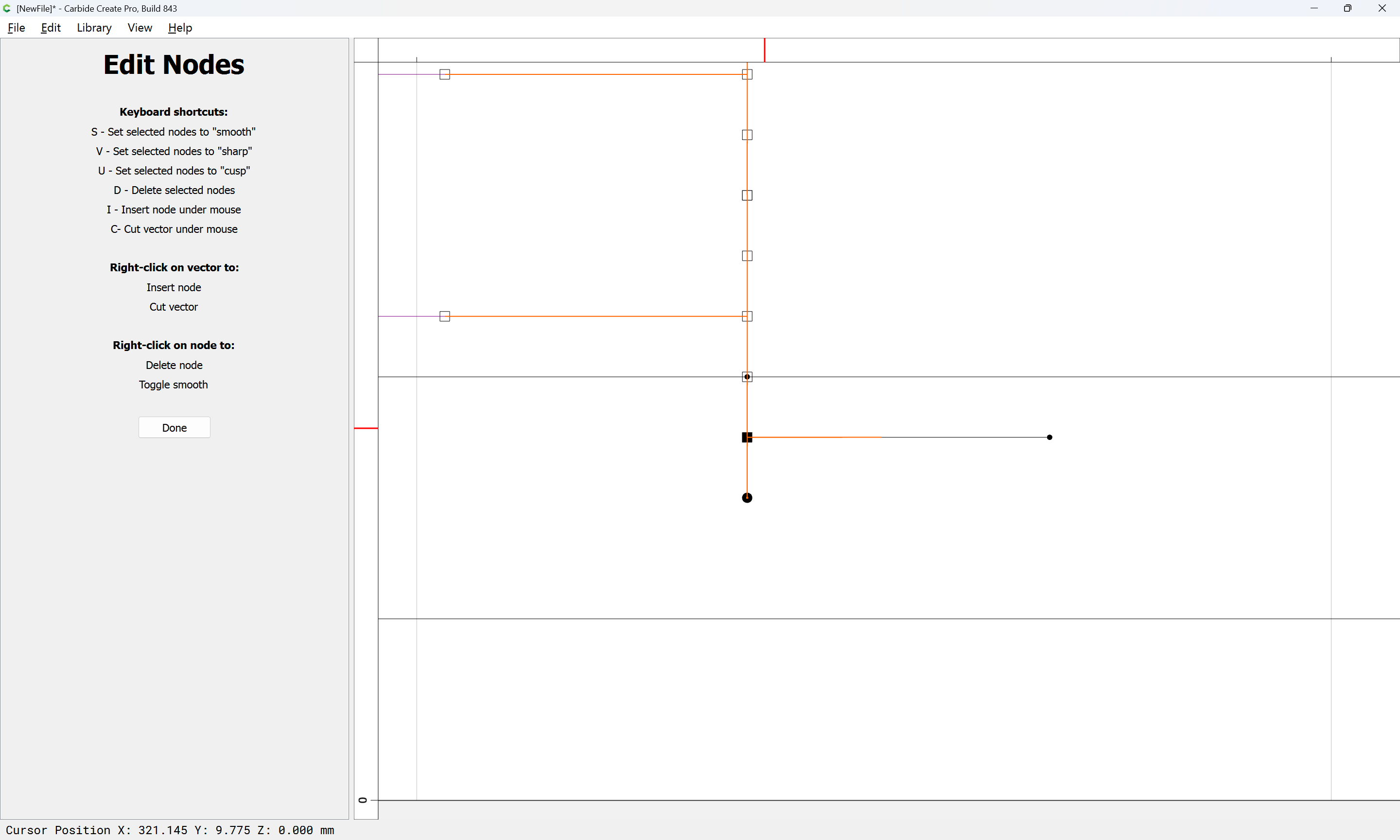
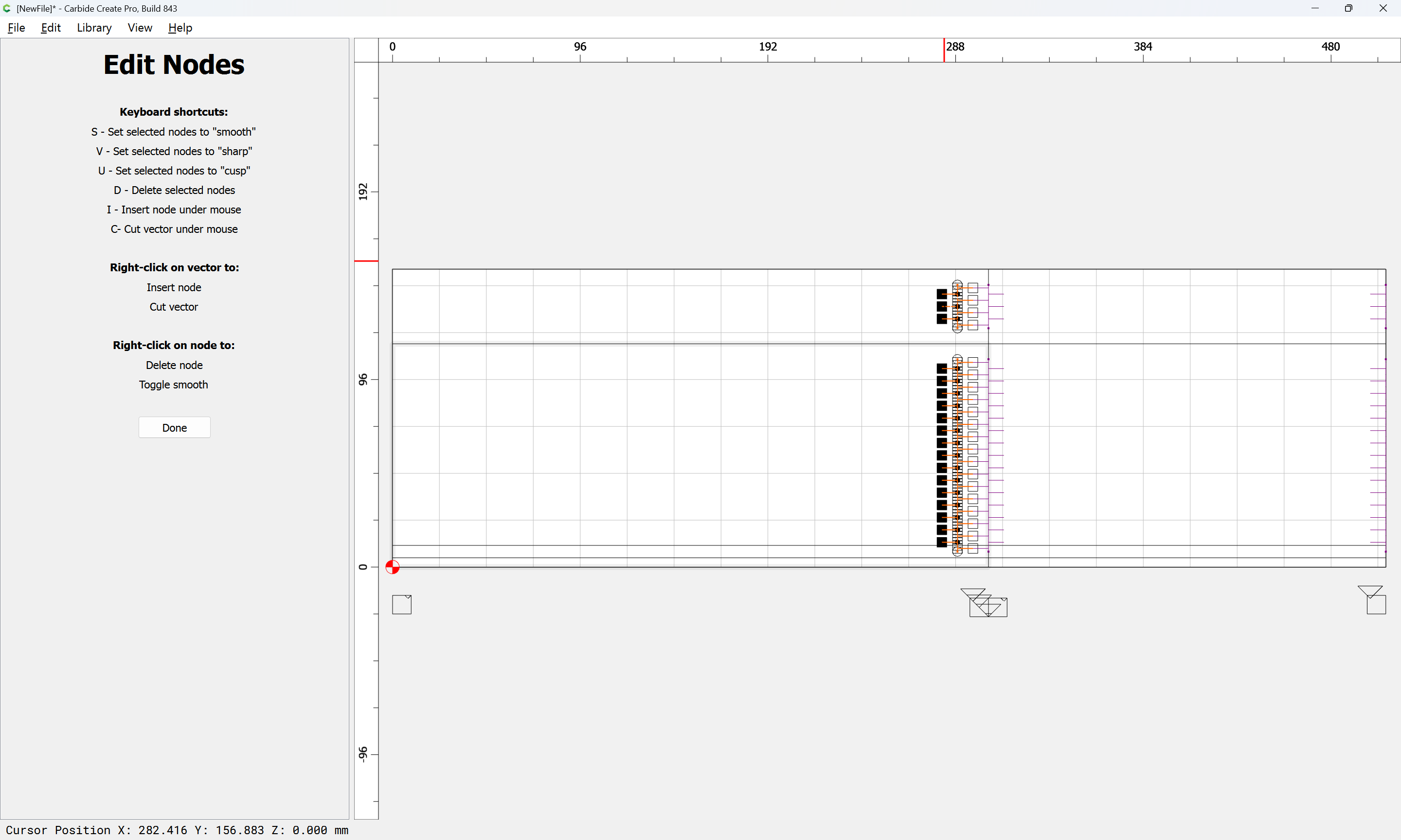
and then Node Edited to remove the one extra recess:
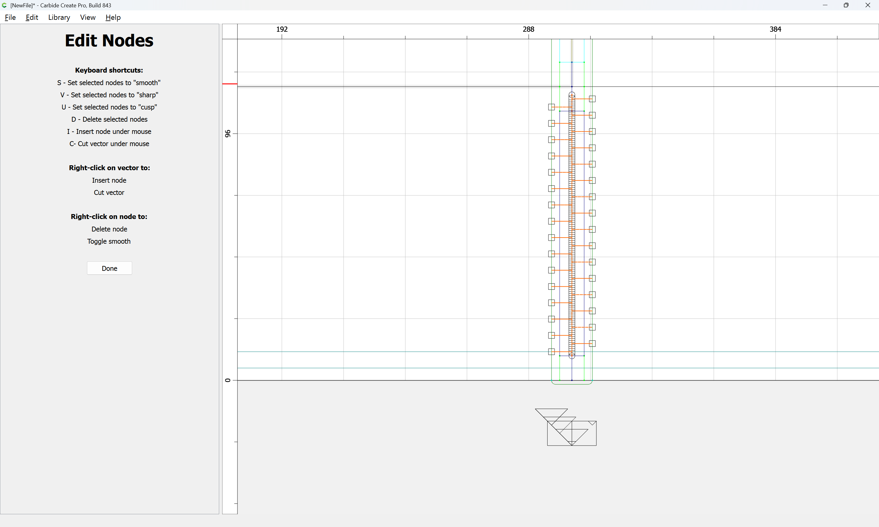
d
Done
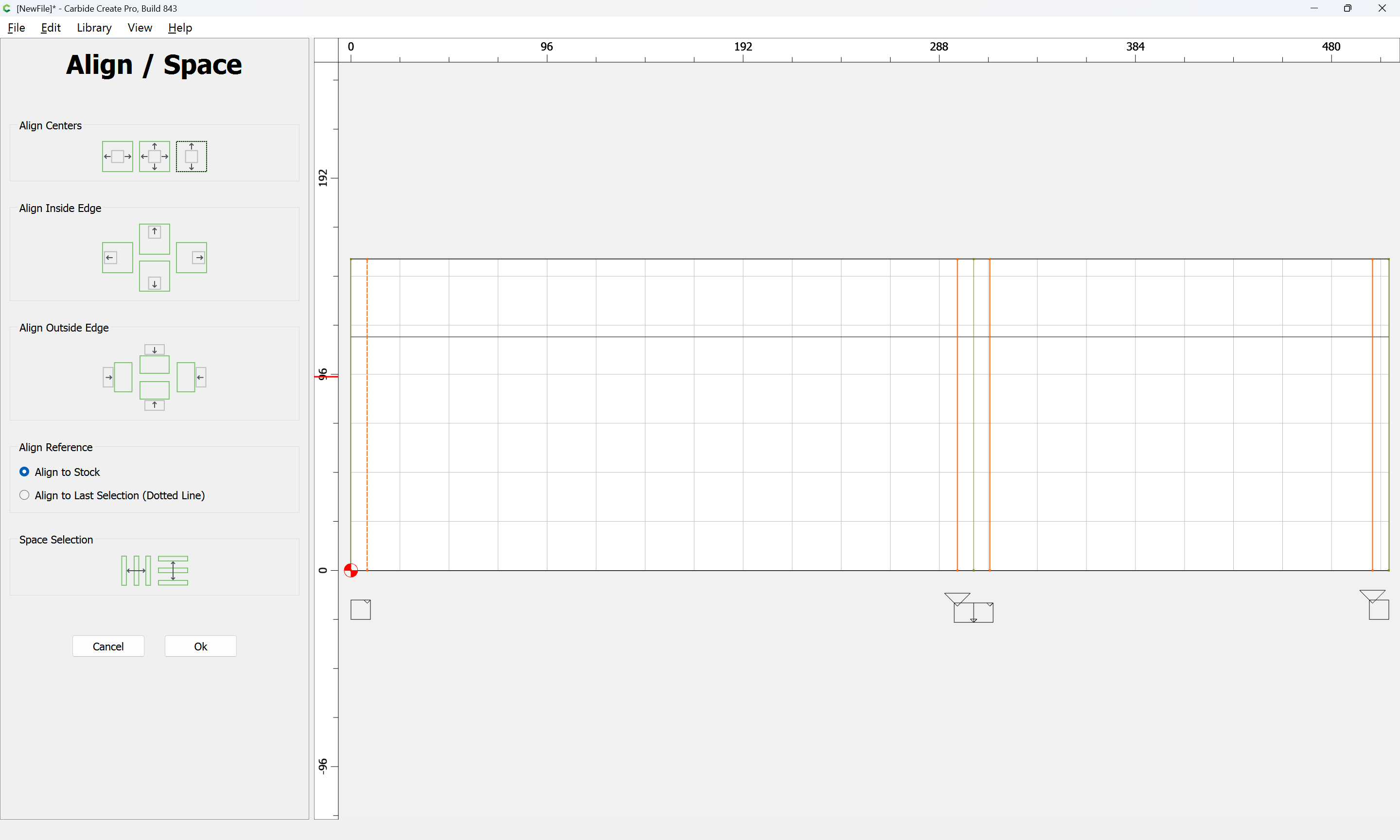
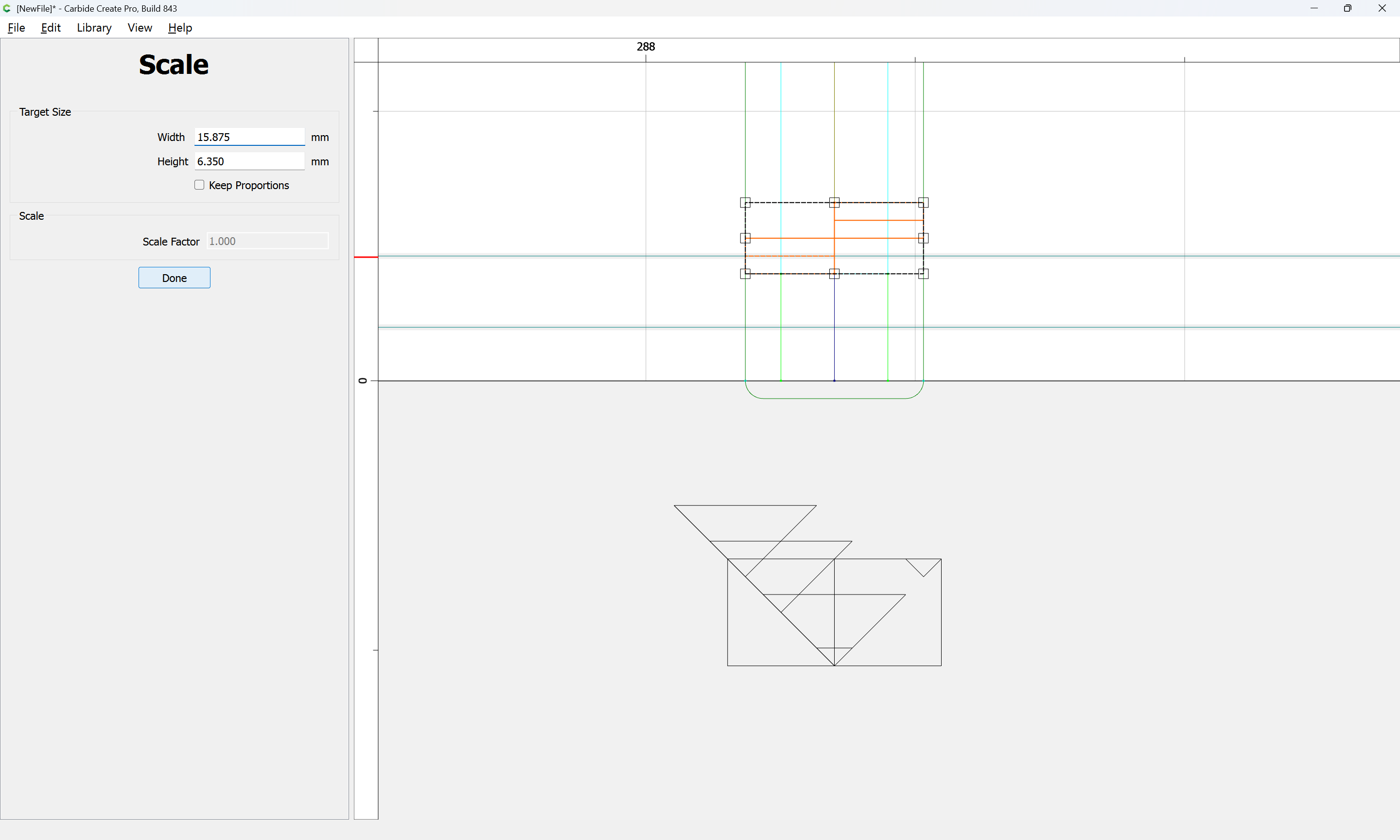
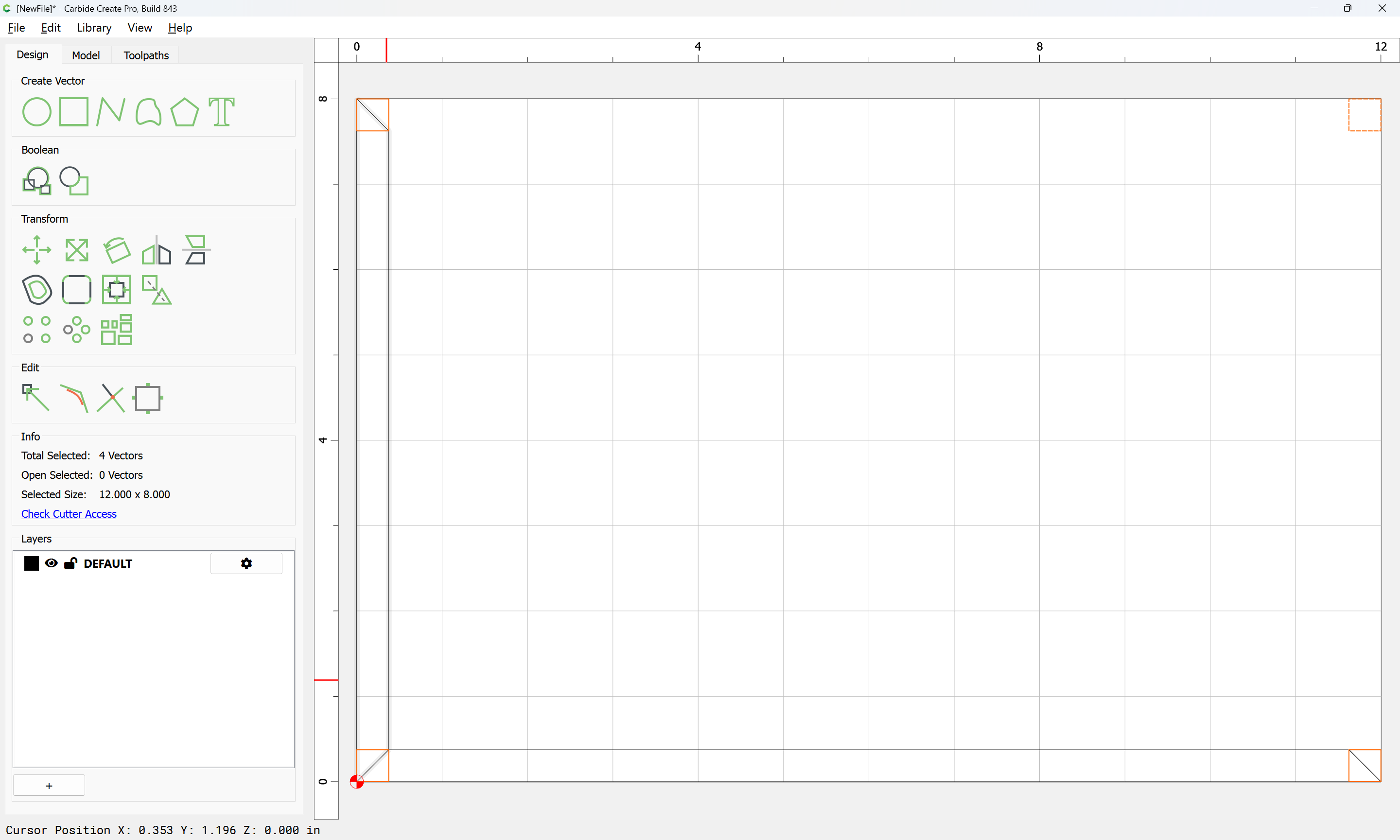
Then aligned vertically with the rectangle drawn in to describe the region:
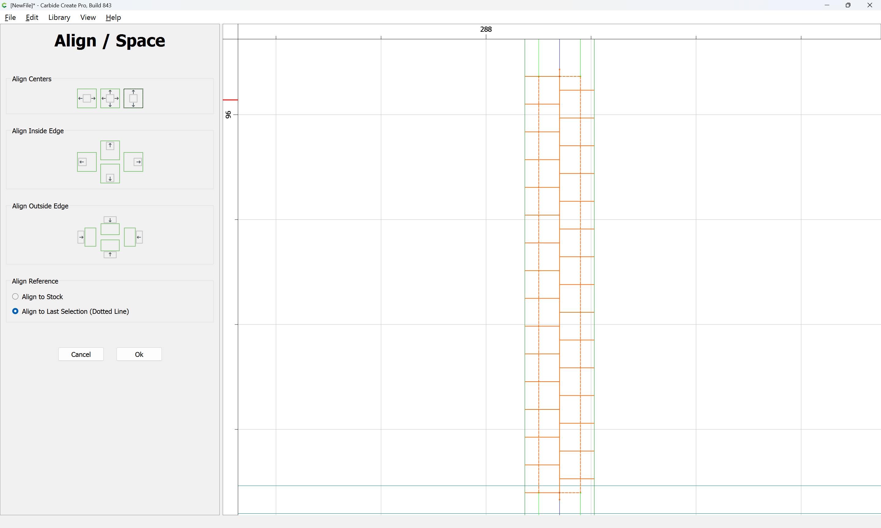
Ok
and the rectangle deleted:
This is then repeated for the upper portion:
and then they are duplicated for the other portions which will each require a suitable half of the recesses:
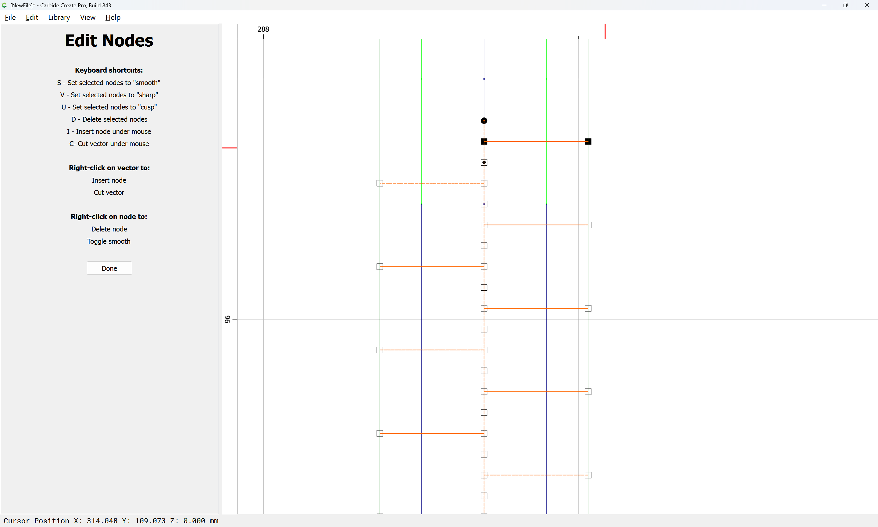
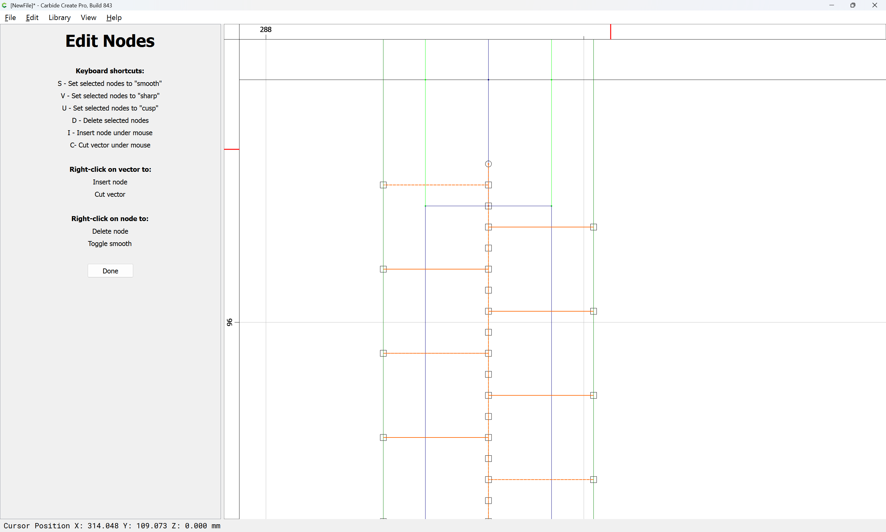
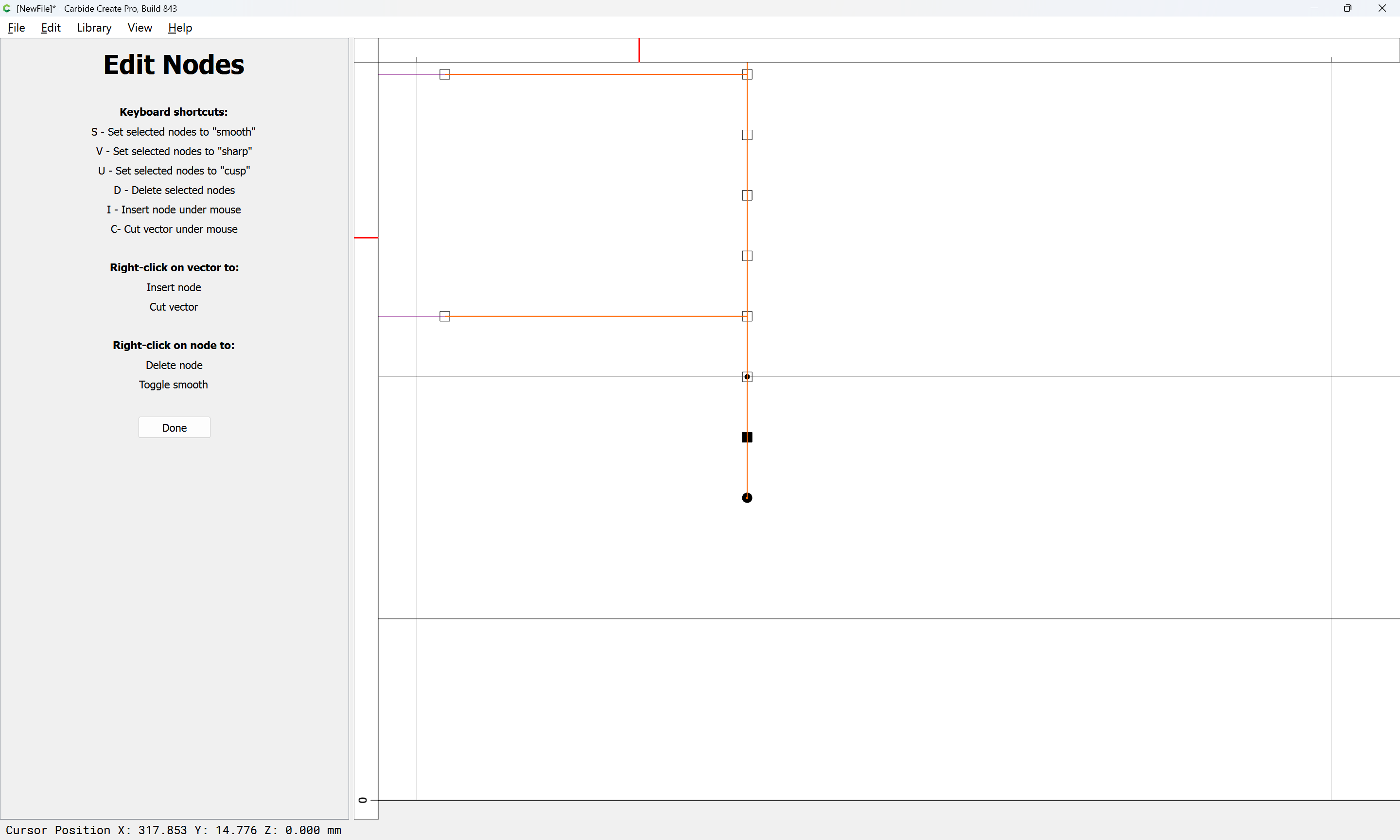
Using Node Editing, each added set of geometry may be trimmed down to only what is wanted:
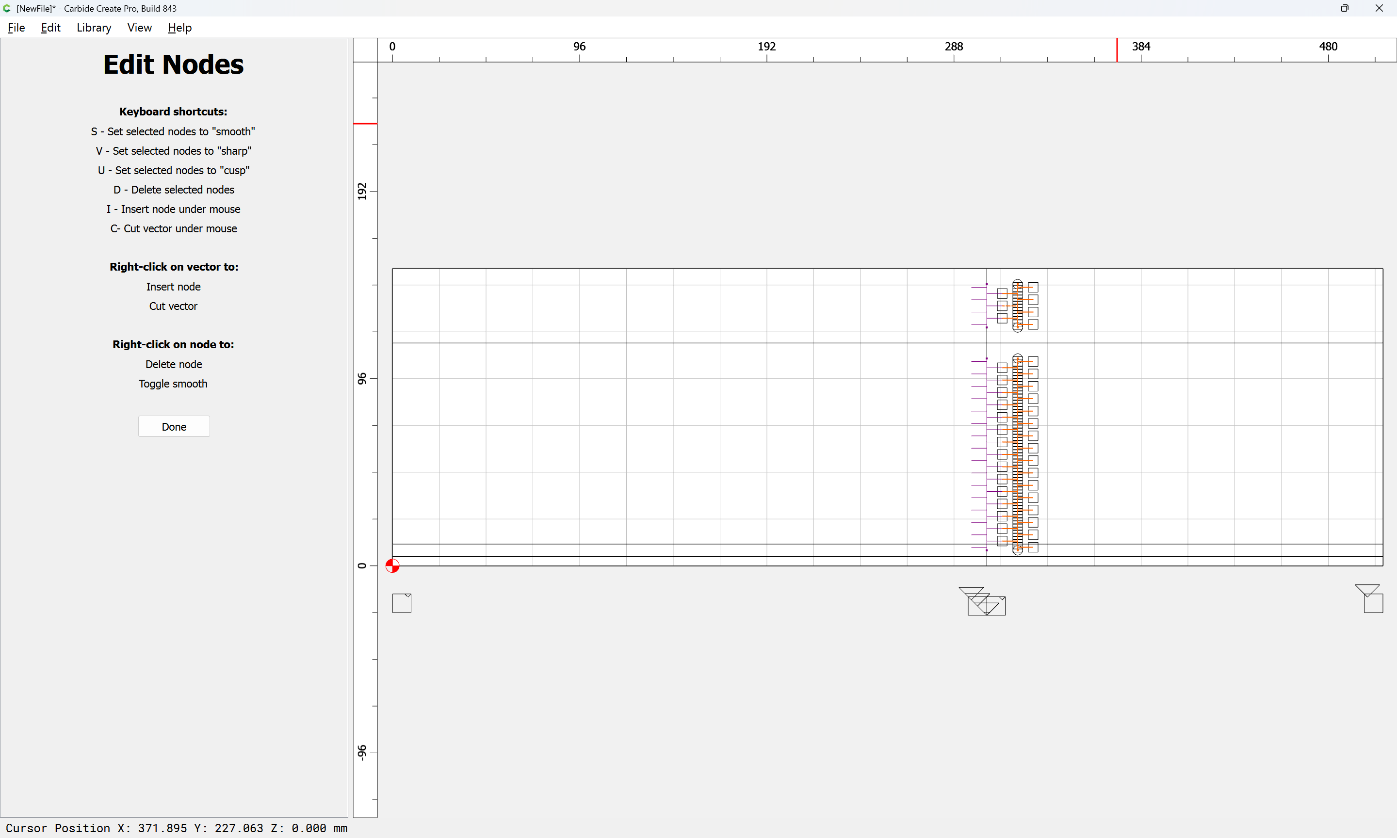
d
Done
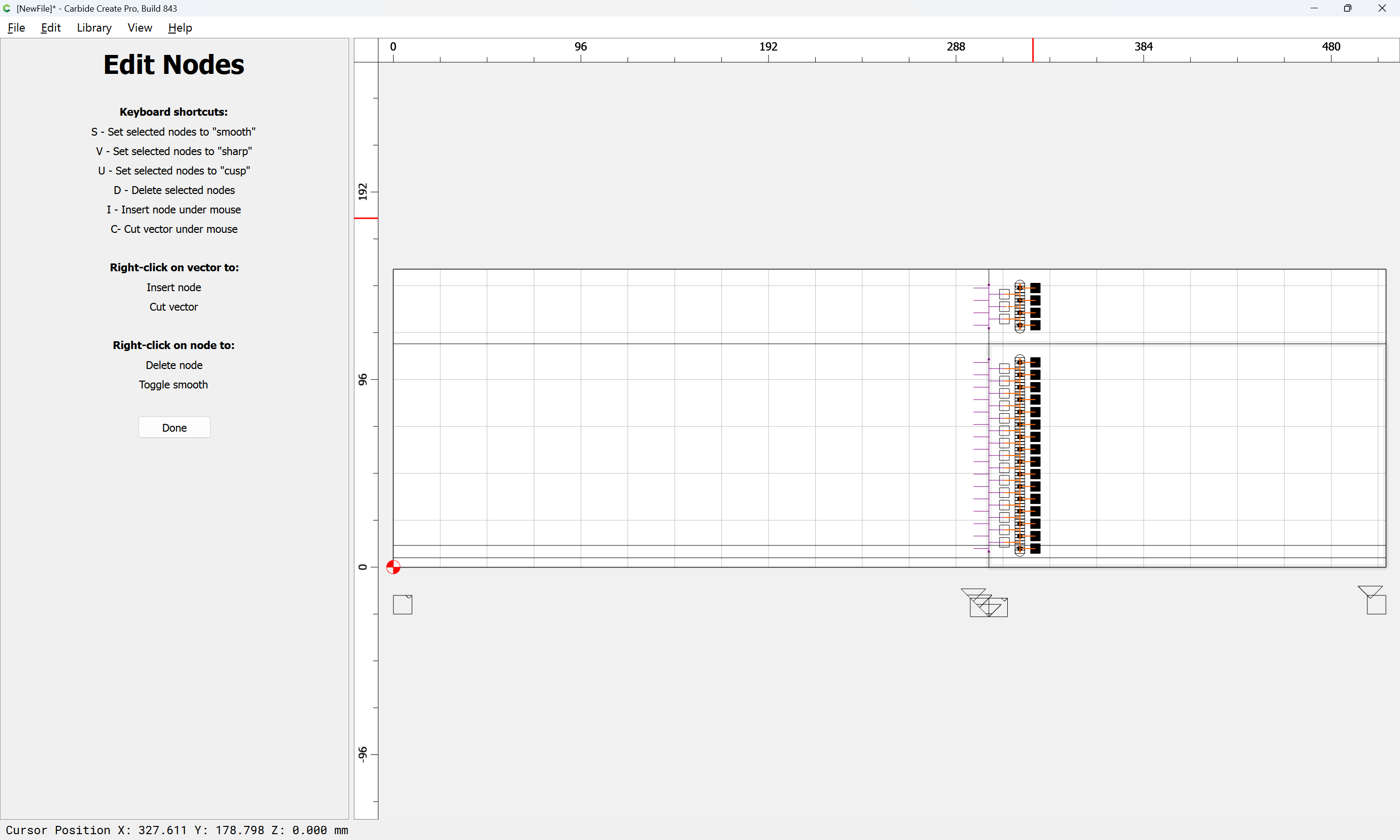
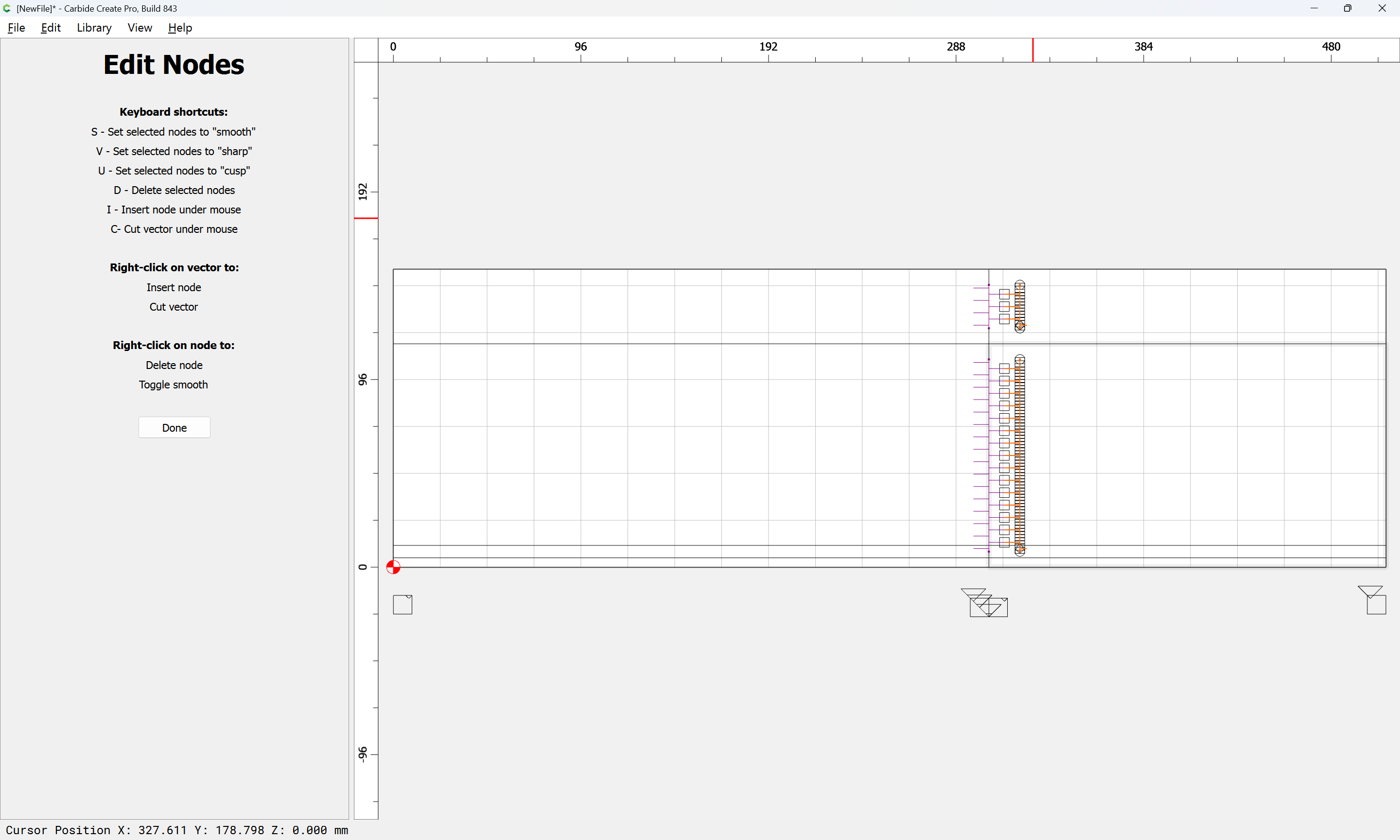
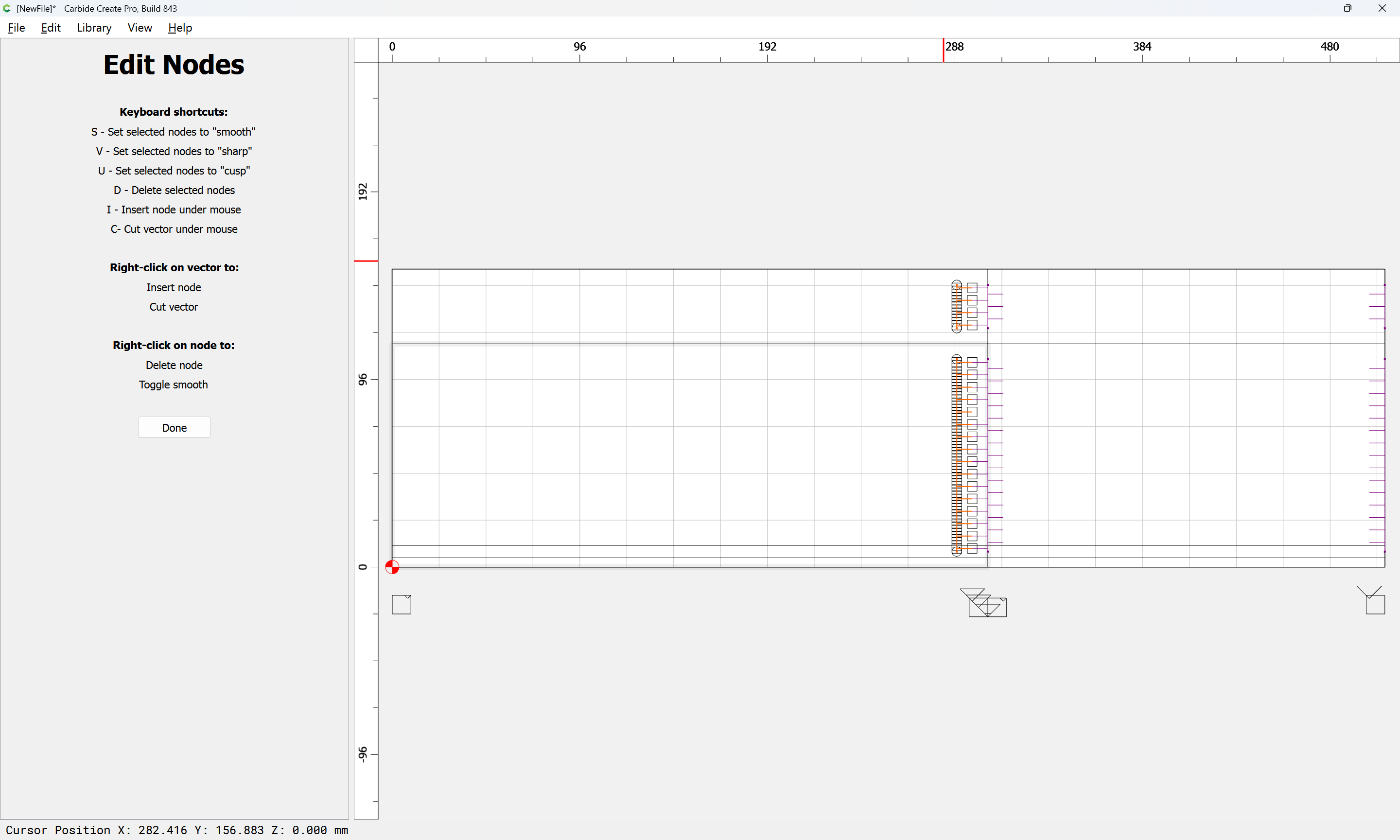
If a given node results in the wrong shape, use Node Editing to select it:
and set it aright:
v
Done
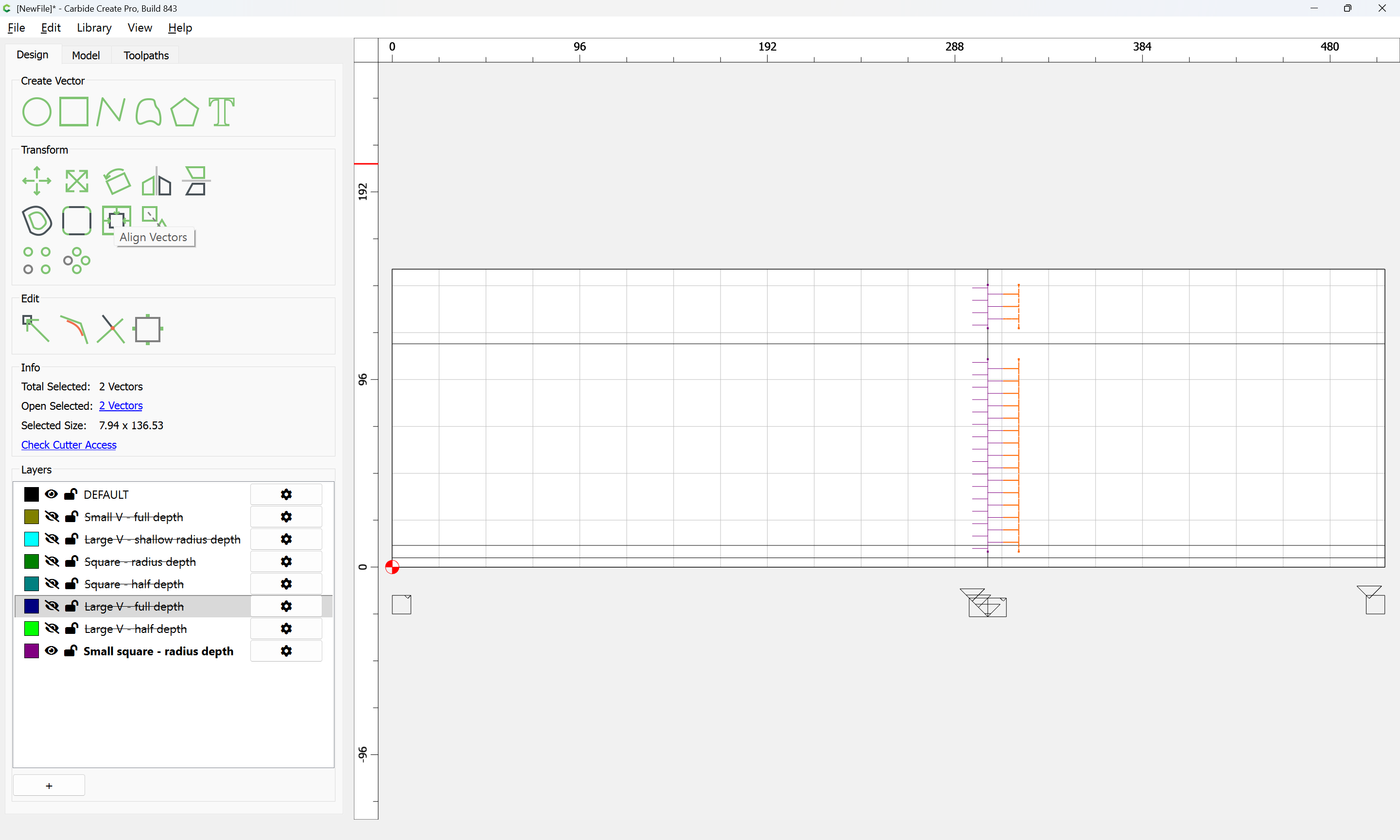
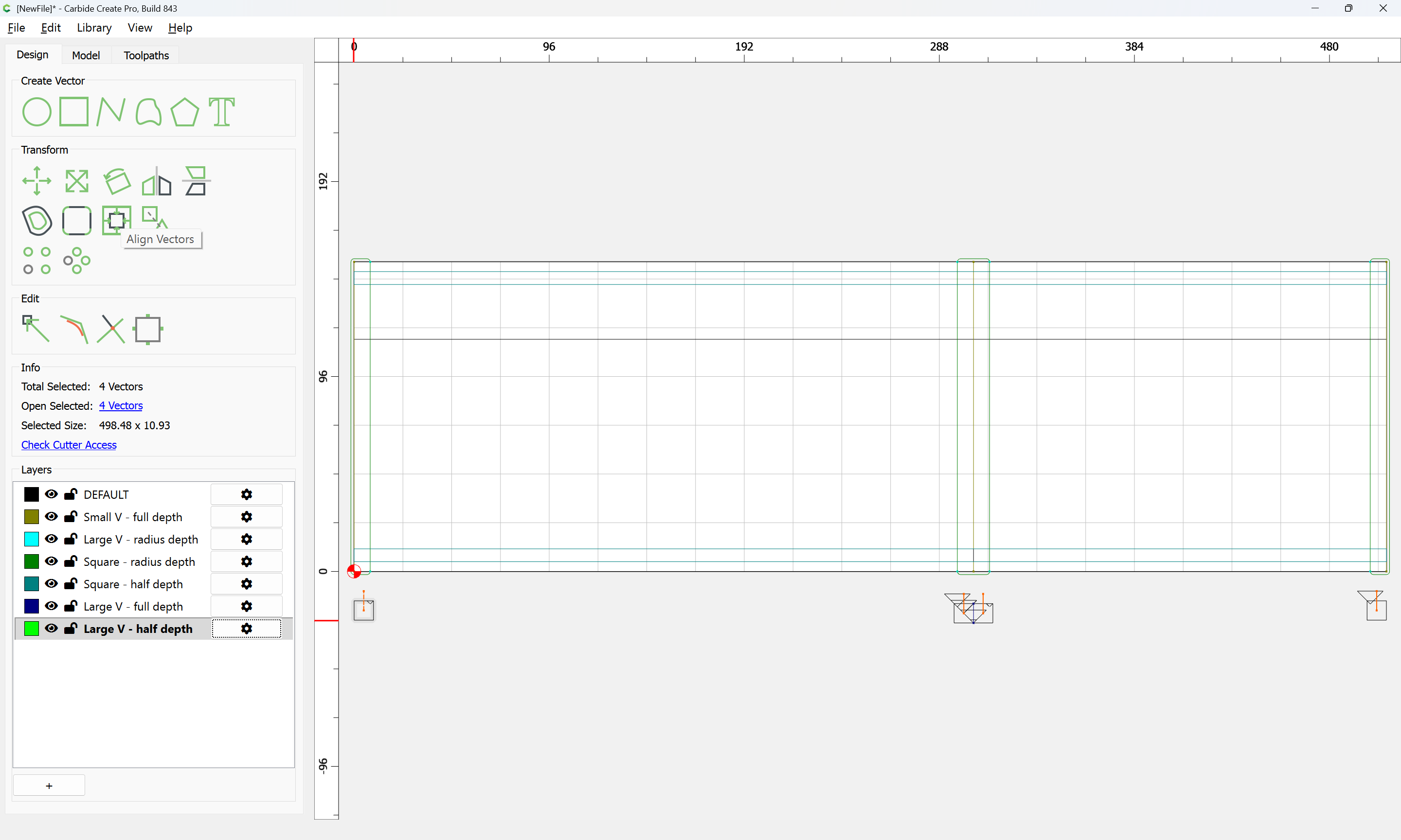
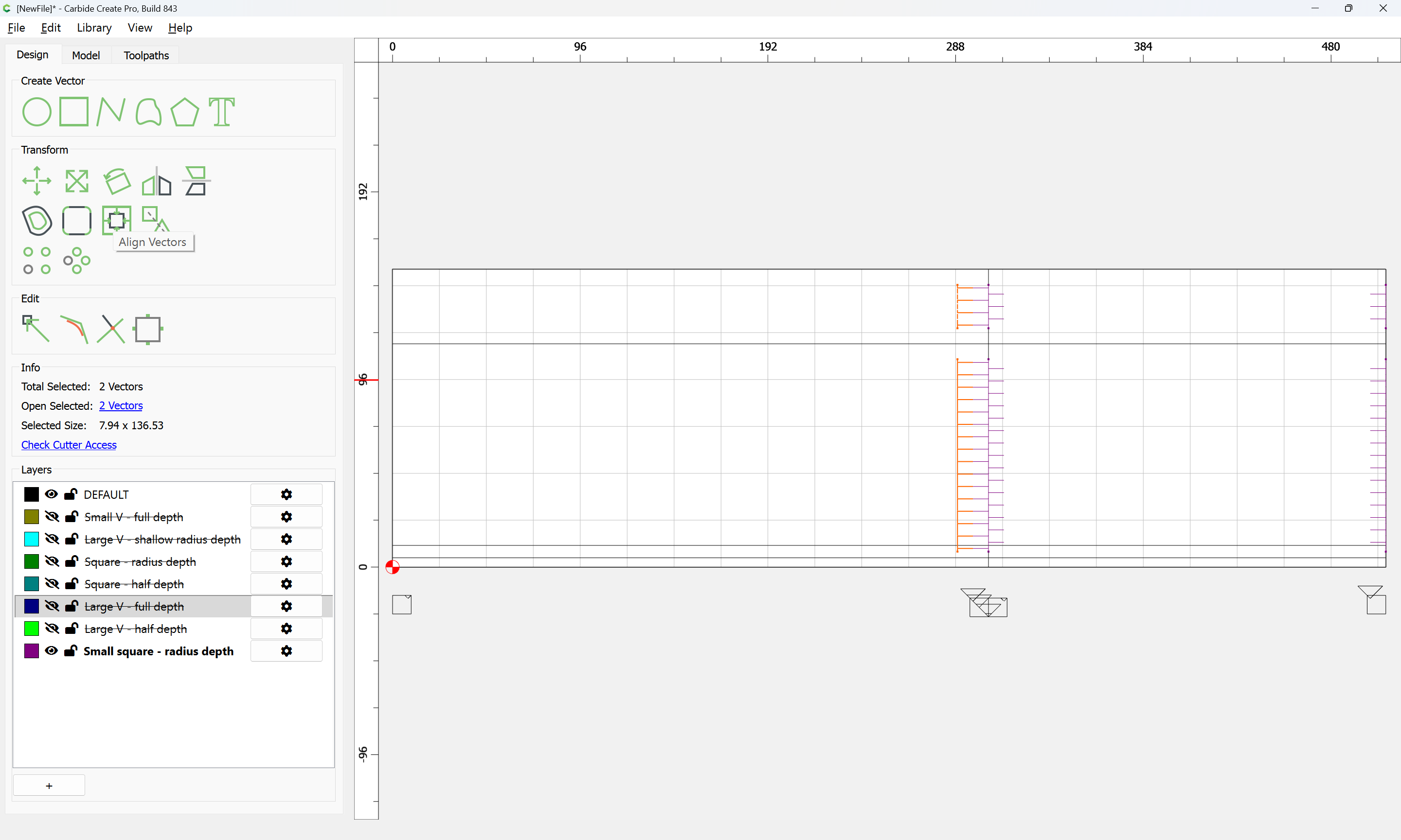
Align Vectors may then be used to position each such added section:
Ok
d
Done
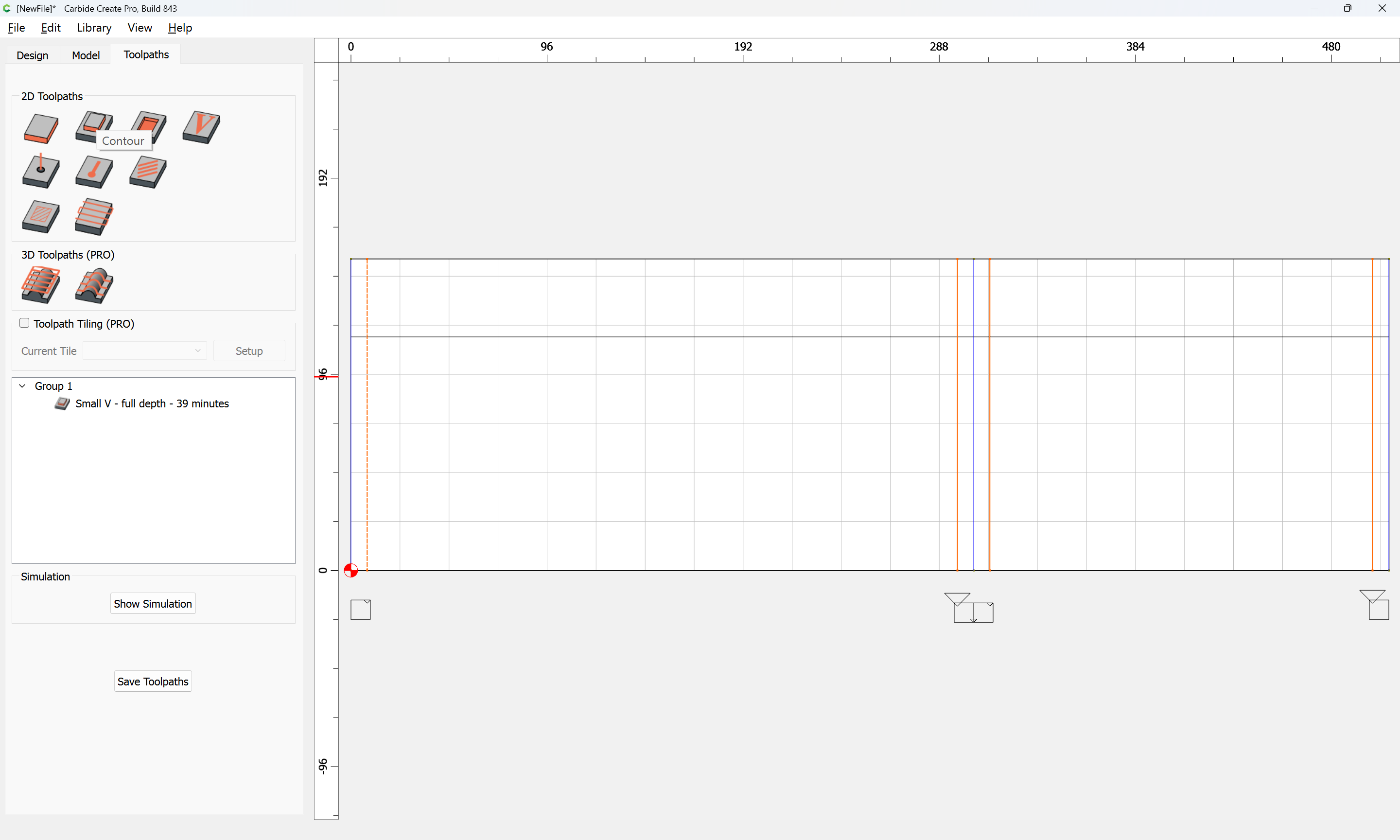
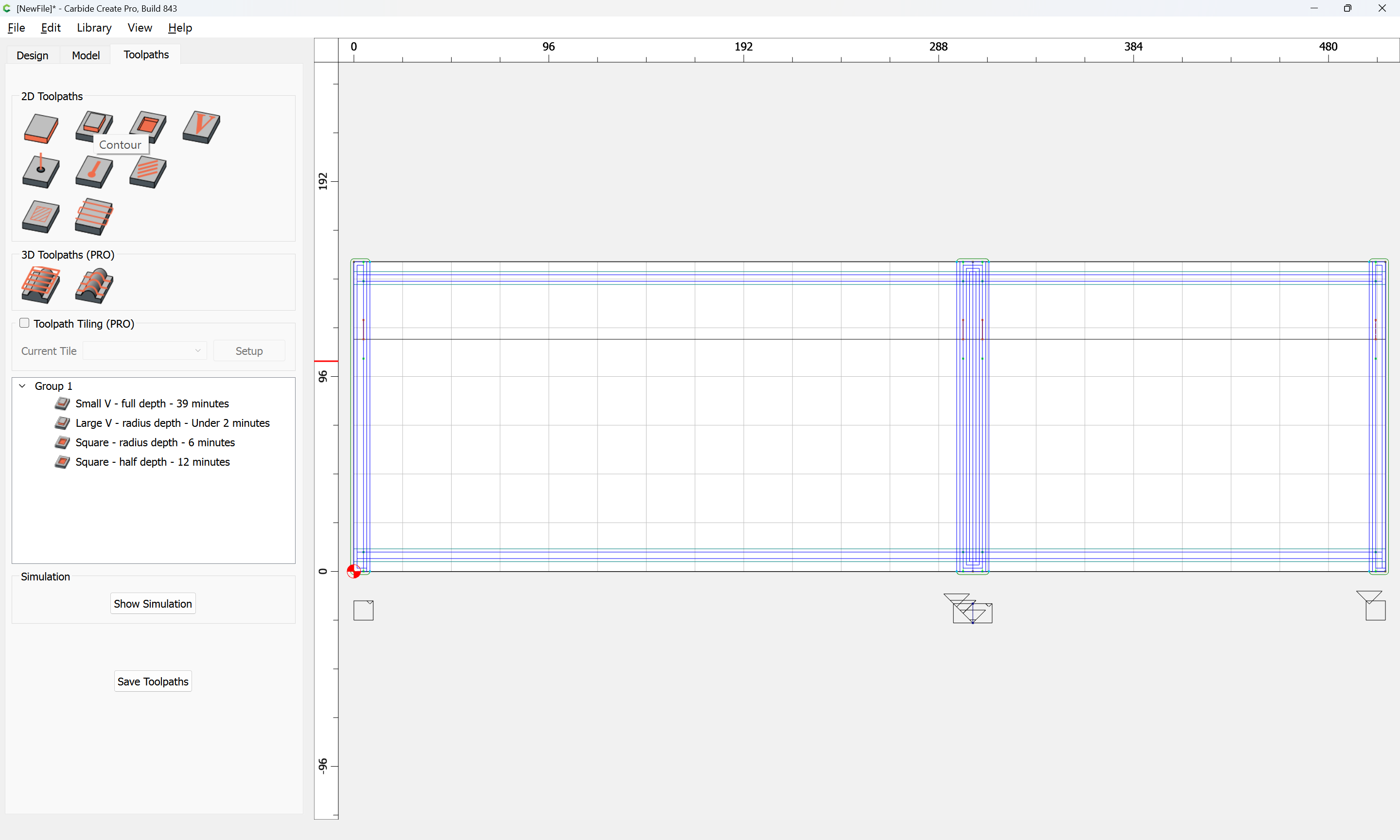
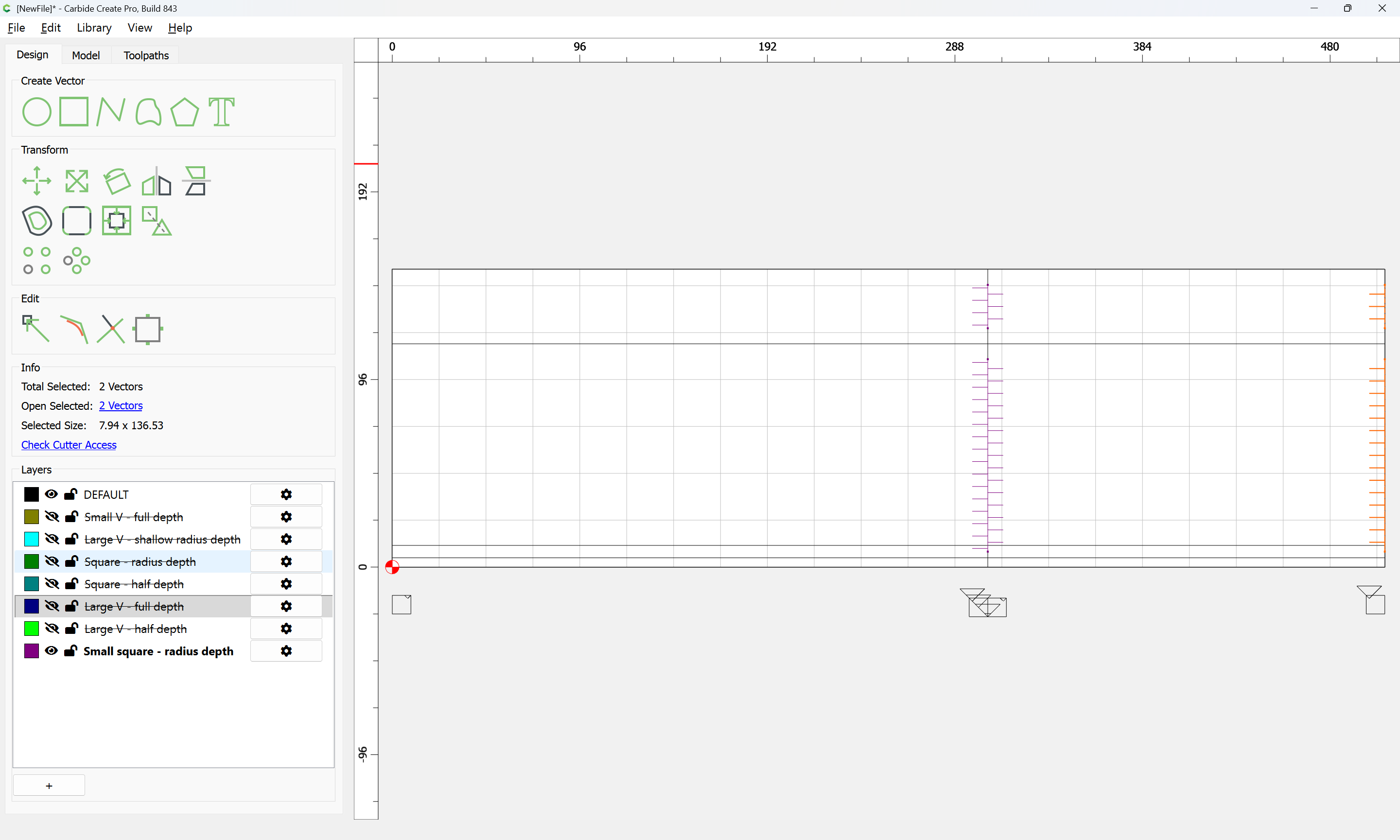
Then, assign a toolpath:
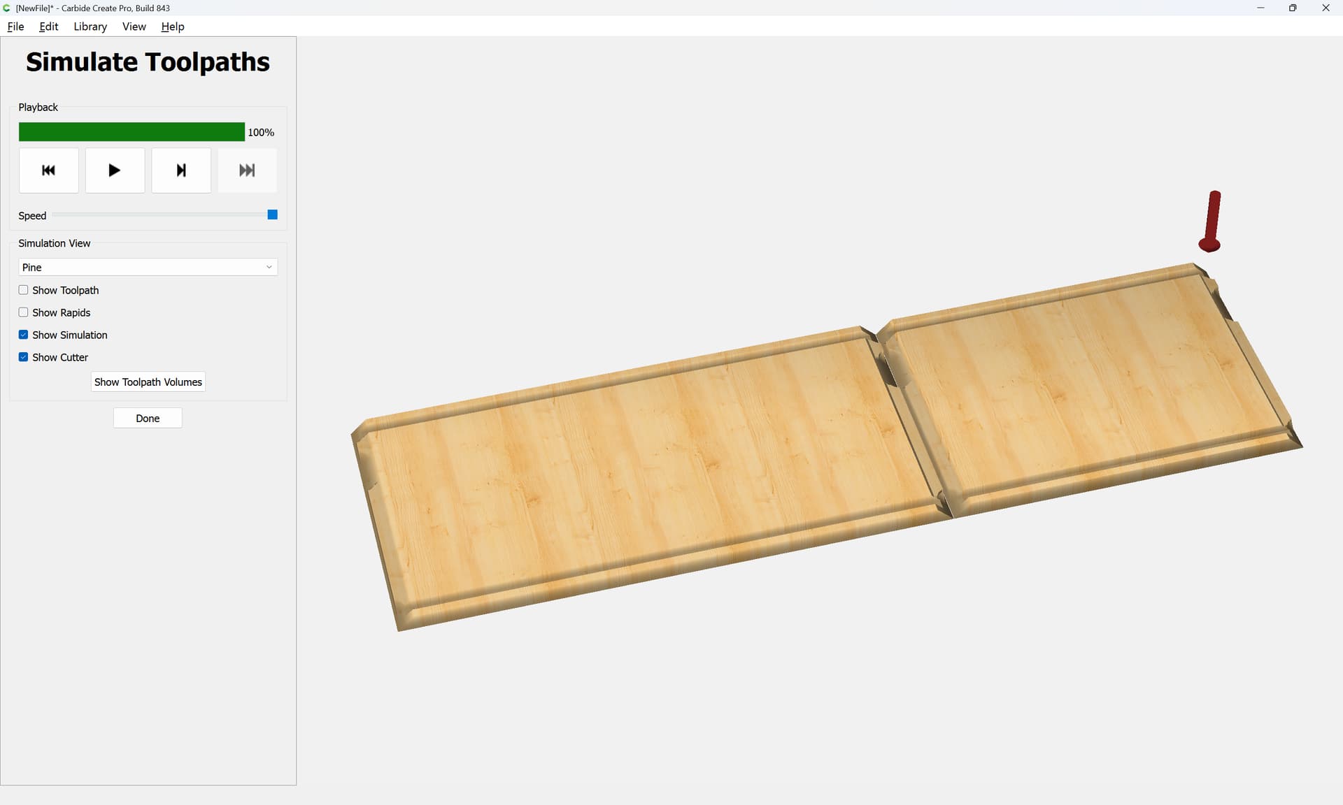
which previews as:
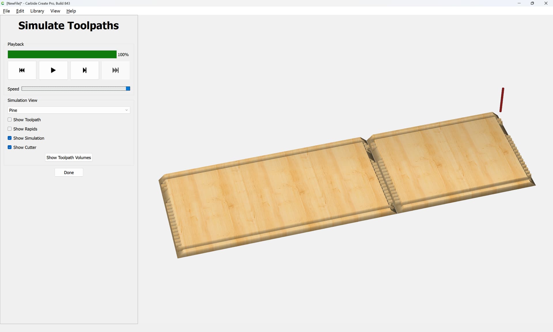
and which when cut, should fit together as expected.
Please test in a piece of scrap before committing to an expensive piece of stock.
box_12x8x6_sawn_v8.c2d (100 KB)
The top and bottom should be obvious and are left as an exercise for the reader.
3 Likes
It is worth noting that the toolpaths will want to be ordered and adjusted for optimizing tool changes and for cutting depth/material removed — a further optimization might be to edit geometry so as to avoid redundant cutting, as defined above, the Small V and Large V full-depth cuts have some overlap. This too is left as an exercise for the reader.
1 Like
Or, one can just write a computer program using my tool:
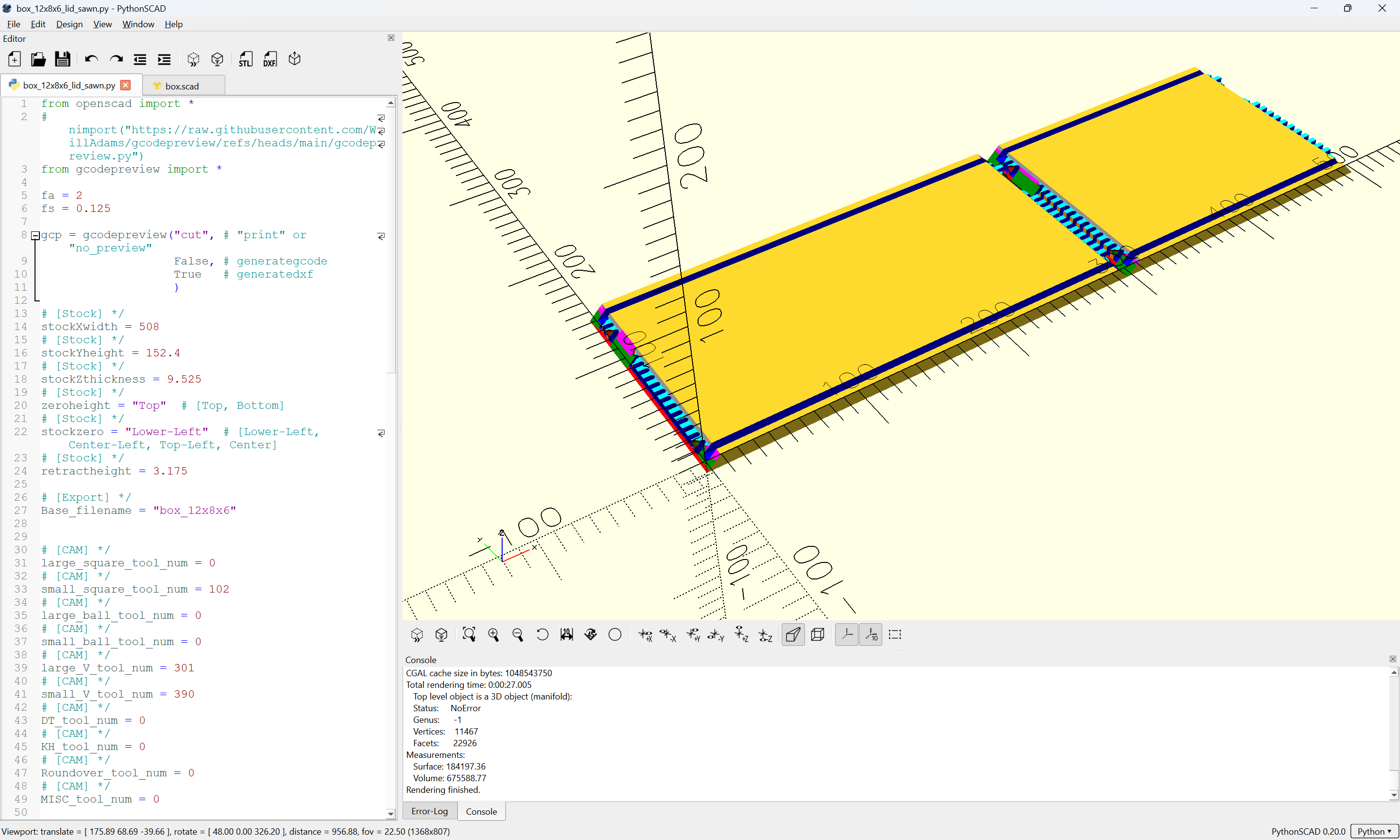
(which is still mostly in the proof-of-concept/working out interfaces/testing phase — waiting for feedback, &c.)
2 Likes
Hi Will,
First of all, thank you for all that you have done. I will do a test piece for the “box_12x8x6_sawn_v8.c2d” today or tomorrow. I know you said the top and bottom pieces are obvious. I’m sorry, but I’ve already gotten a little lost. (I’m a beginner!) Would you mind posting the files for those, please? It’s easier for me to digest if I have the instructions, as well as the actual files.
Thank you,
Roy
Draw an overhead view of the parts:
Cut this out:
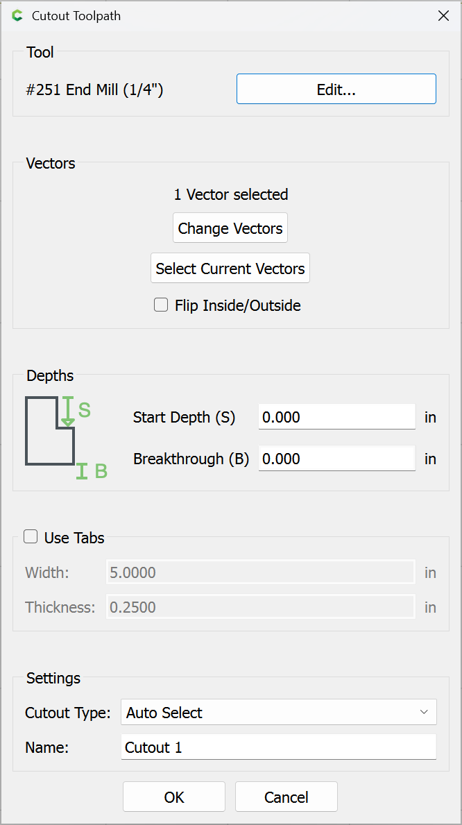
using a workholding setup such as blue painter’s tape and cyanoacrylate glue which will allow forgoing tabs.
Attached as a v8 file.
box_12x8x6_sawn_LID_v8.c2d (44 KB)
Note that you could optionally use thicker stock and cut it in a decorative fashion, adding rabbets along the edges to allow the top to fit, or at the bottom, creating feet or other features.
1 Like