As time runs down, I should at least START the post for my entry.
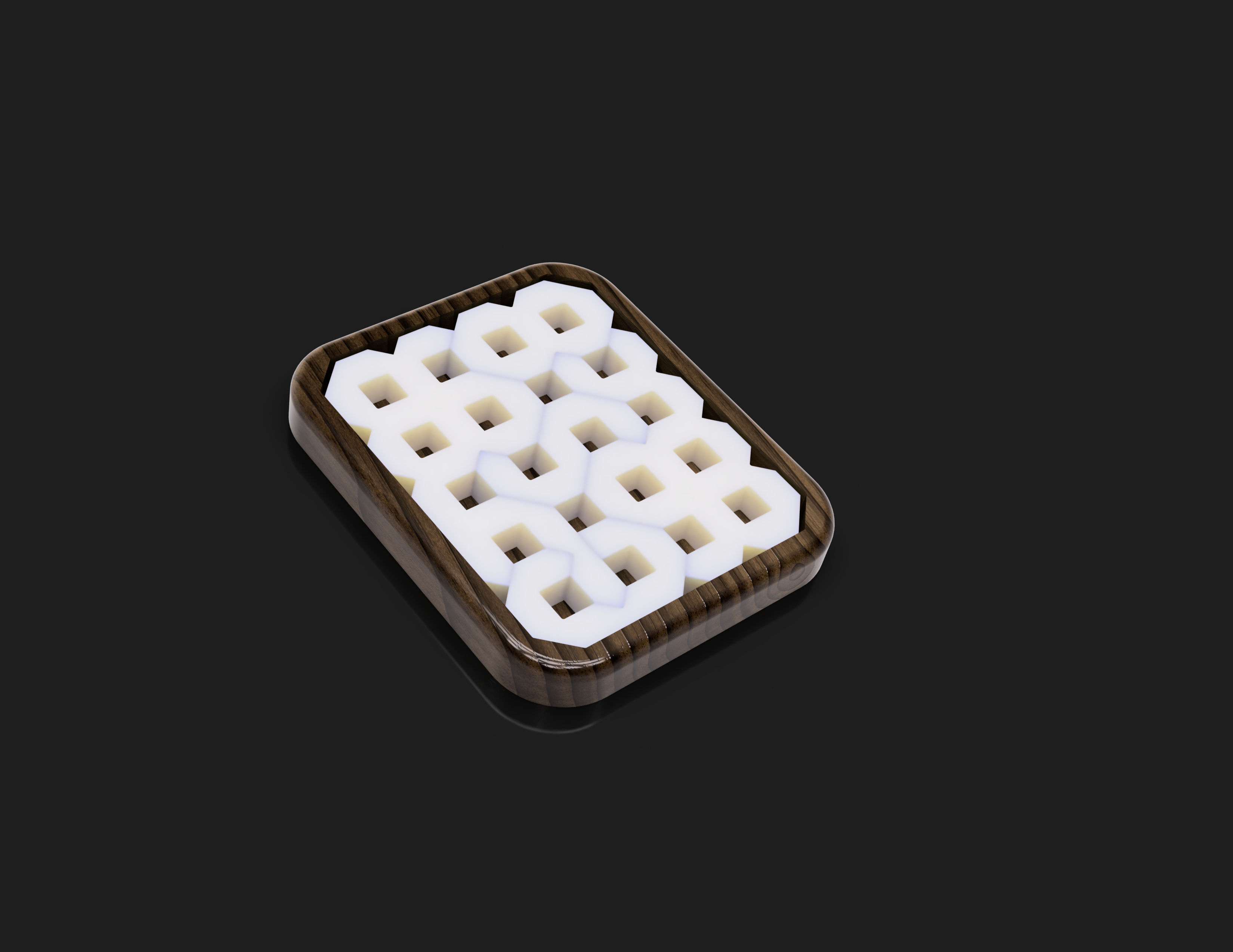
It looks like it COULD be complete at this point, and is actually a rather tough puzzle for most people presented in this form, but there is more that I have yet to complete. I will add the design files later, but for the moment will leave a little mystery with where this is going, though I have no doubt that there are several of y’all that have a good idea. In the end, there is a twist, though.
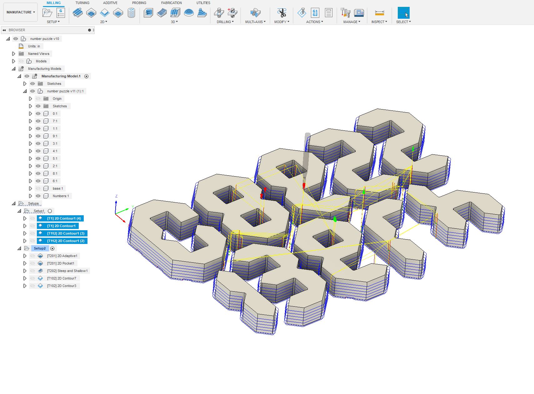
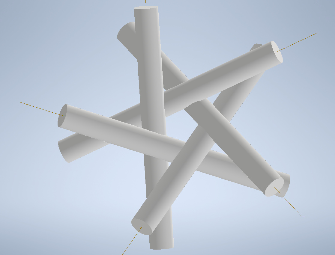
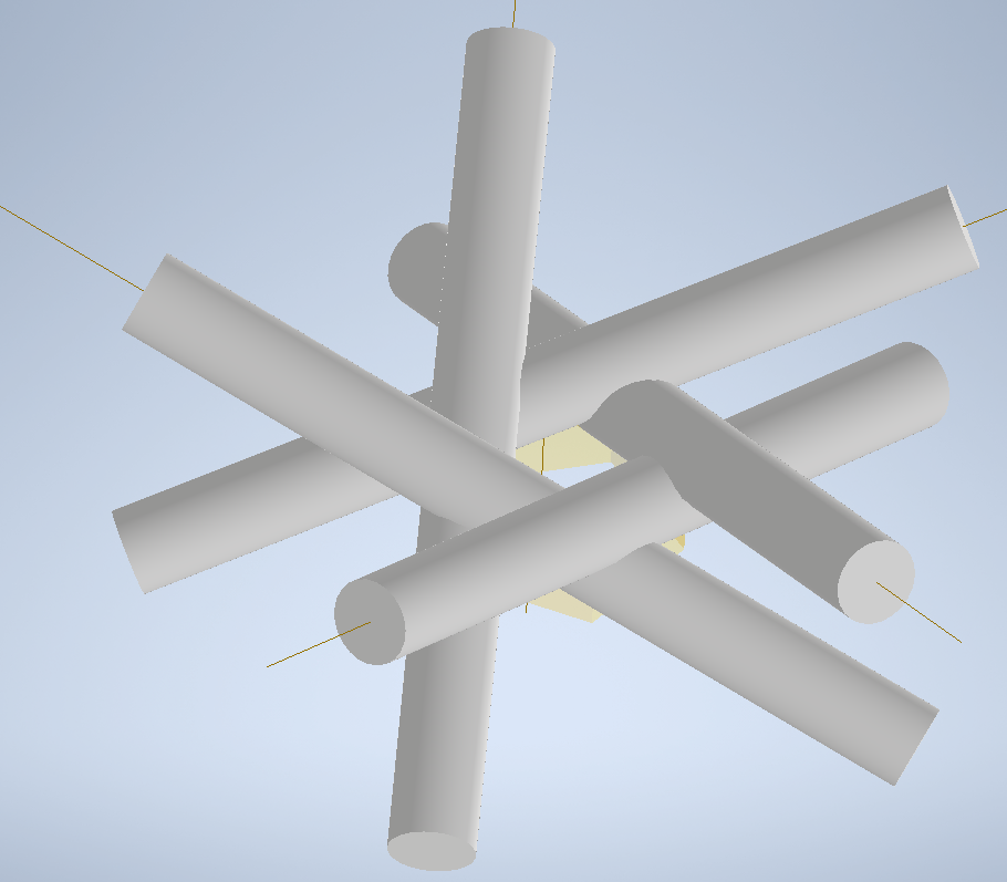
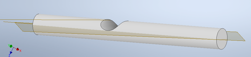
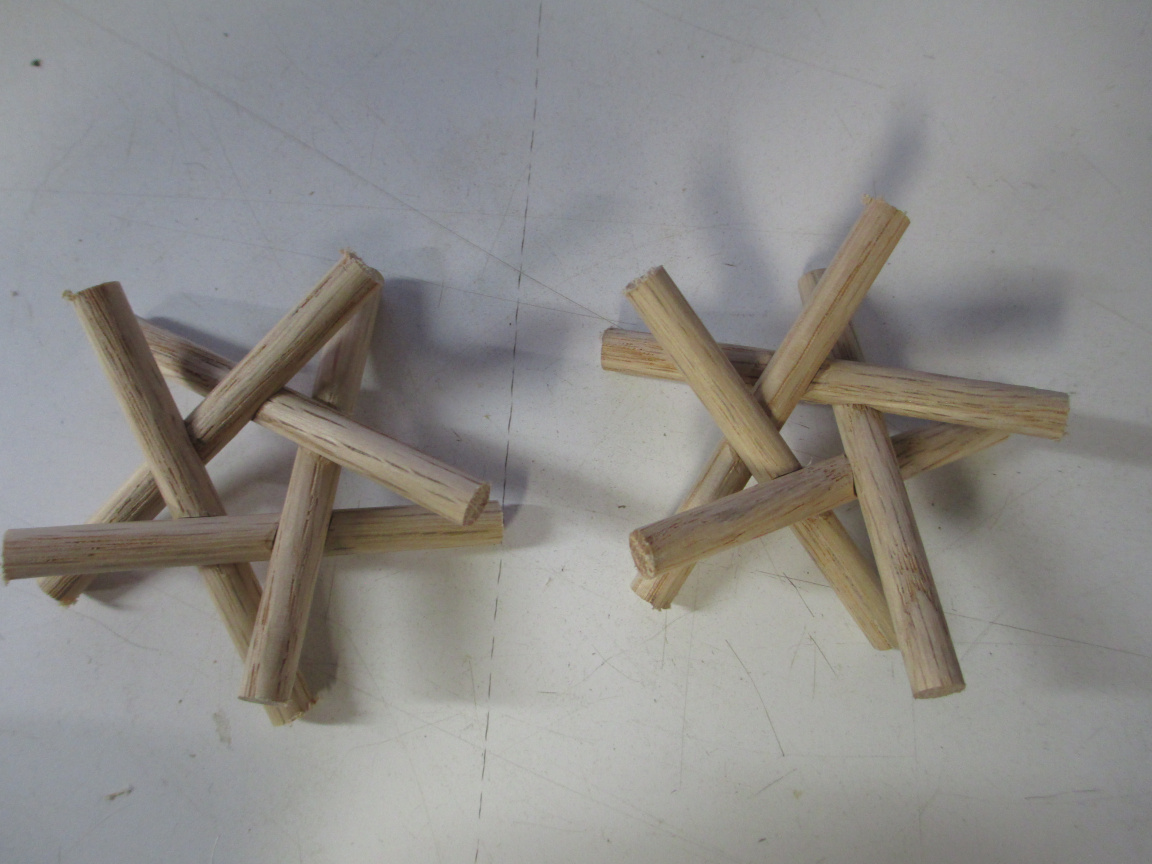
The general form is interlocking rods. I used oak dowels here, though the final version will be larger and aluminium. The tolerances on dowels are not great for this. The structure looks like
in CAD. The form is the rods half-through at each intersection, kind of like Lincoln logs, but to make the pentagonal structure, the notches are at compound angles. This made setting up the coordinate system interesting to machine.
\
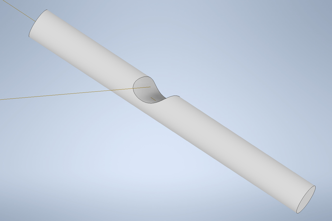
You can see that the rods have the notch, and that I left the axes of both.
And added a work plane ON the axis of the part being cut, PARALLEL to the axis of the intersecting rod. The origin in in this plane, on the axis of the part being cut, but this is not the center axially. This gives a really nice coordinate system to fixture the parts for machining, and allows the notch to have no overhangs.
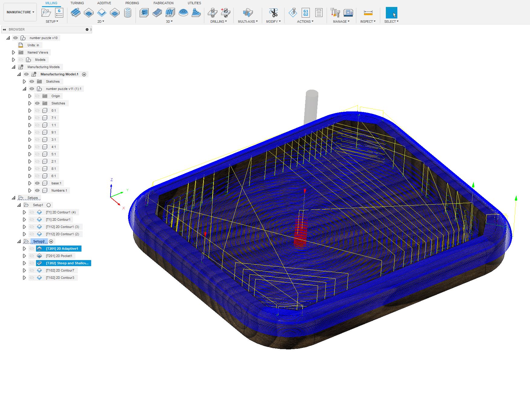
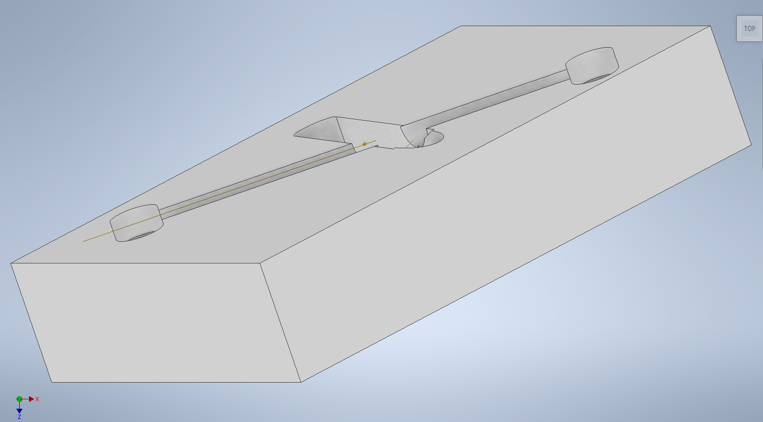
This means the notches will be machined witht he end of the tool, and the finishing will be multiple passes with a ball-end. Not ideal for a great surface, but the other option was fixture the part tilted up, making trimming the ends square a challenge, or requiring extra setups.
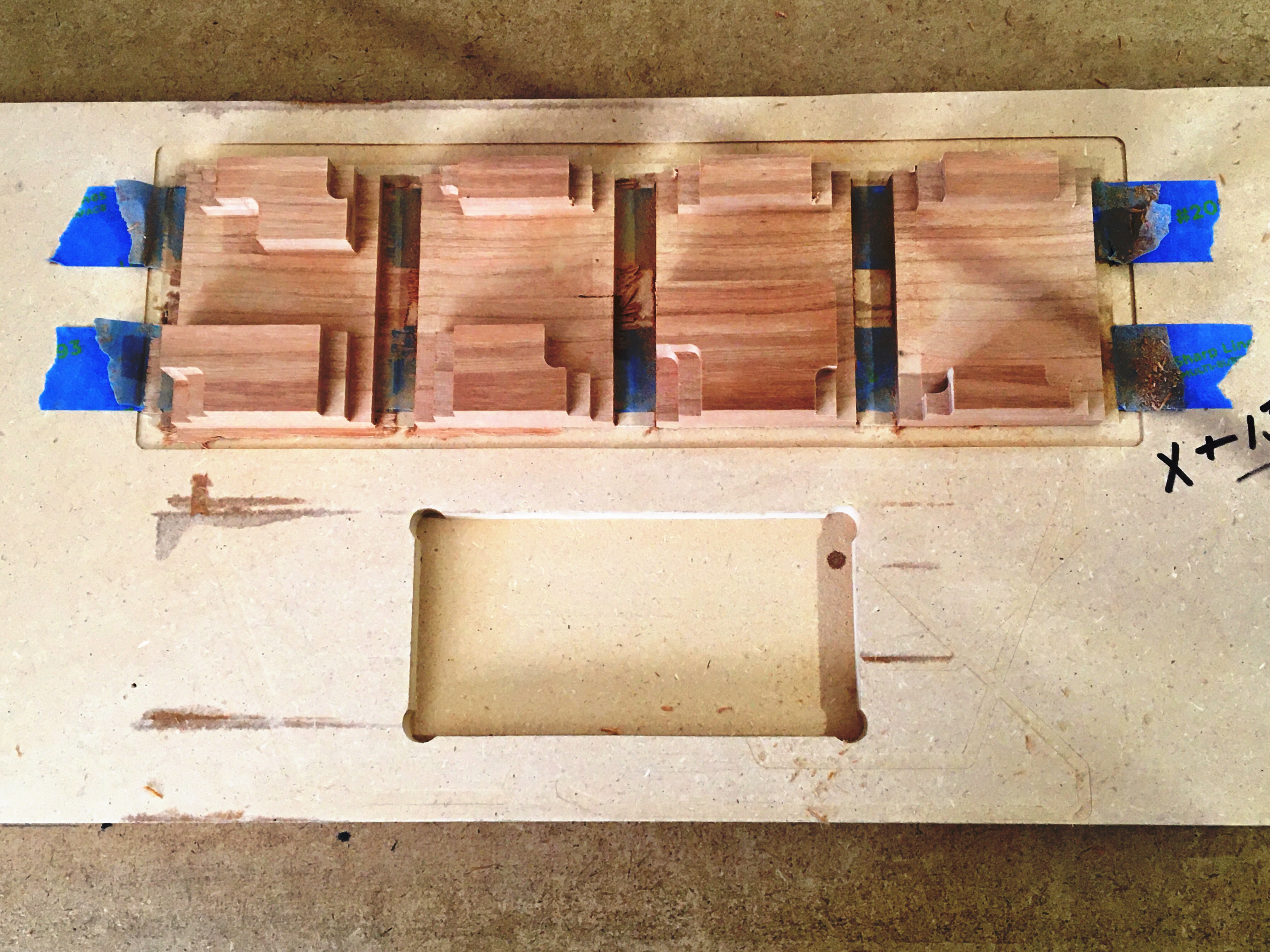
The wells at each end are for trimming to length.
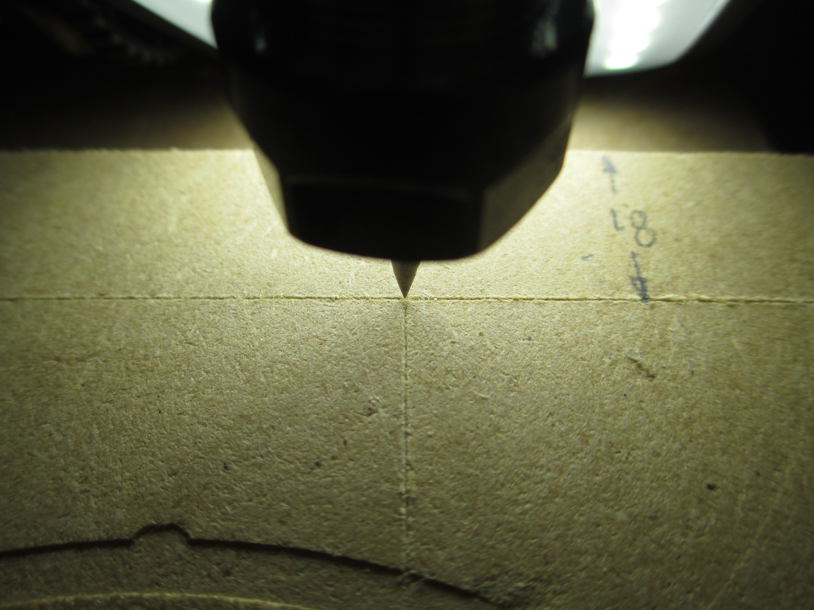
First, glue a riser piece onto the wasteboard (12mm isn’t enough thickness), locate the origin, deck it, and machine the fixture.
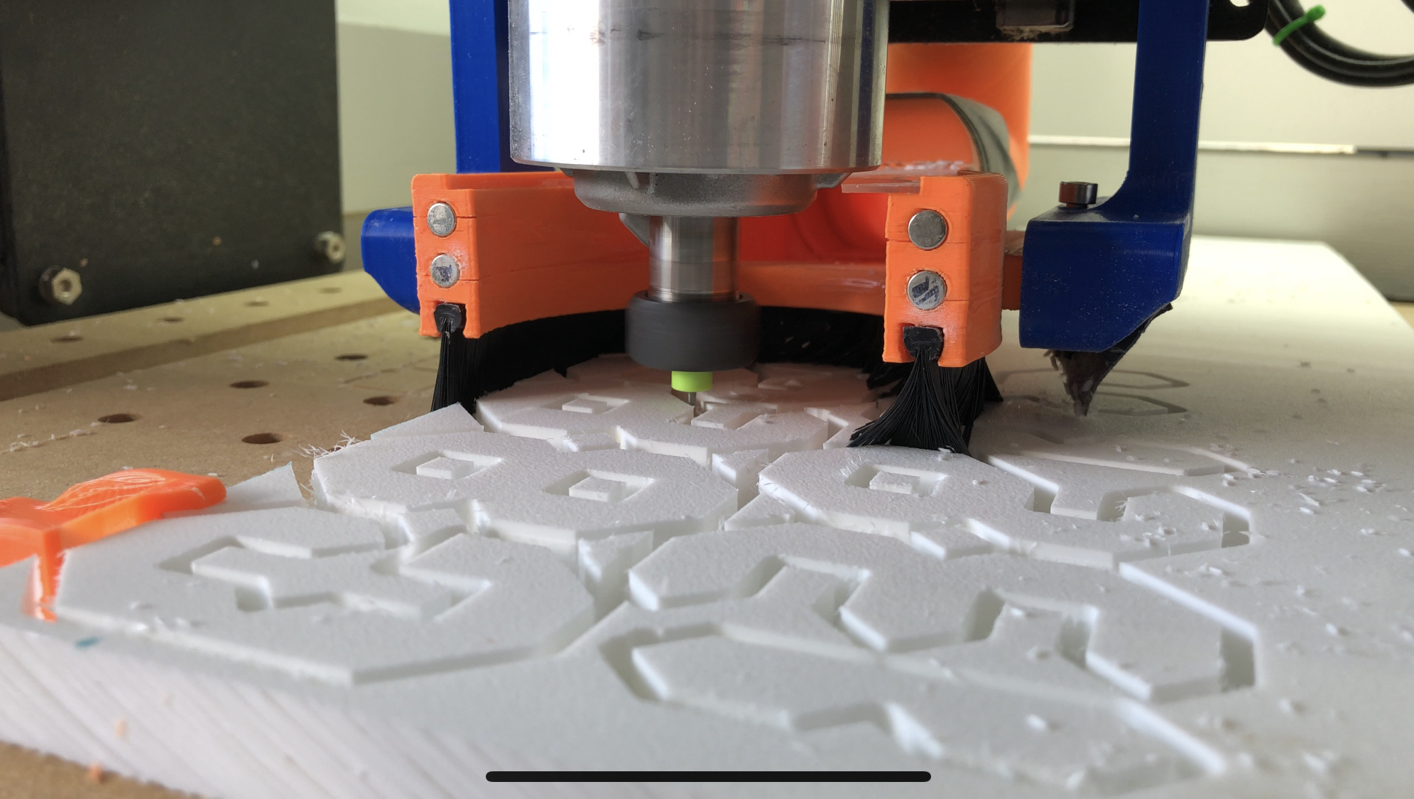
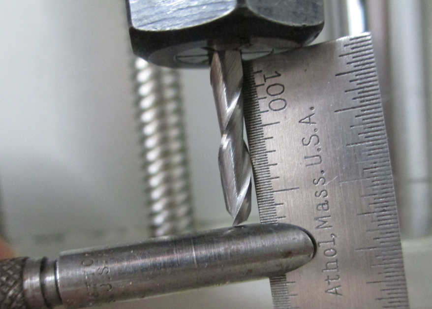
I set the tools to the minimum acceptable extension
leaving about 1mm between the surface and the collet nut
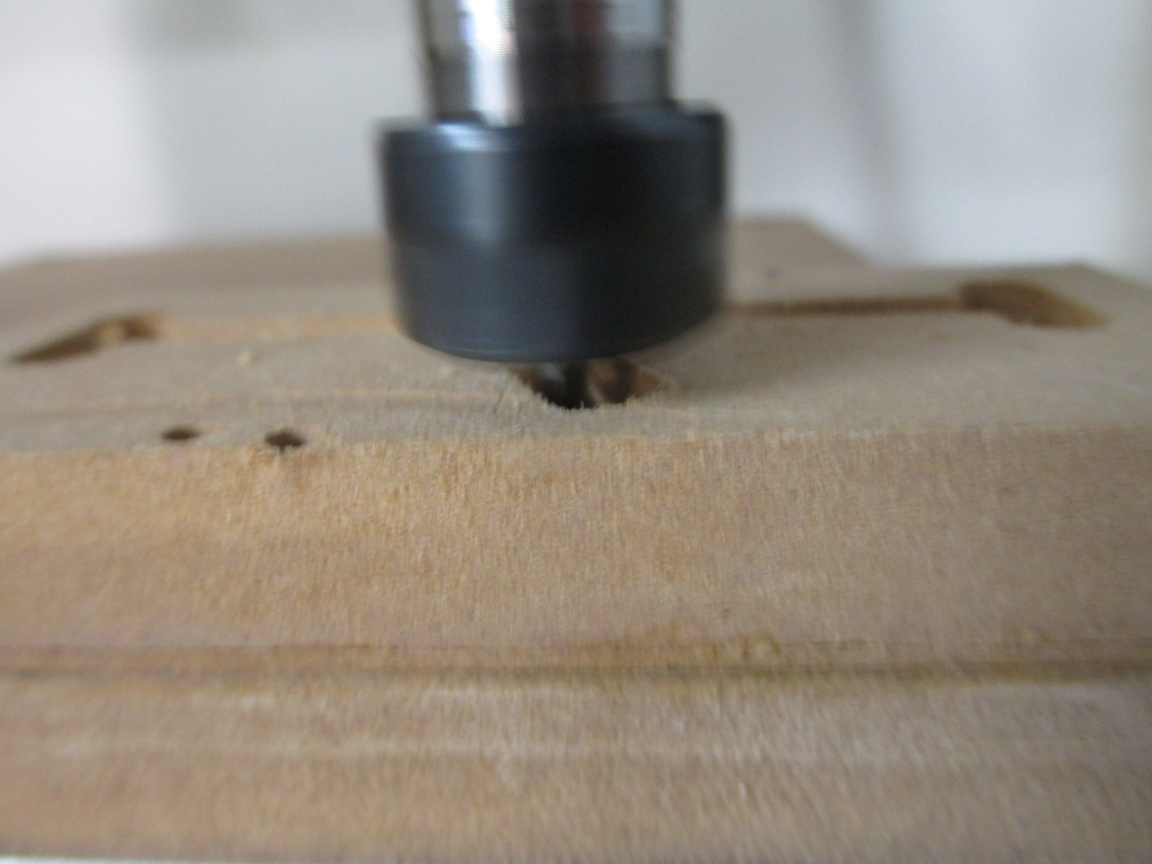
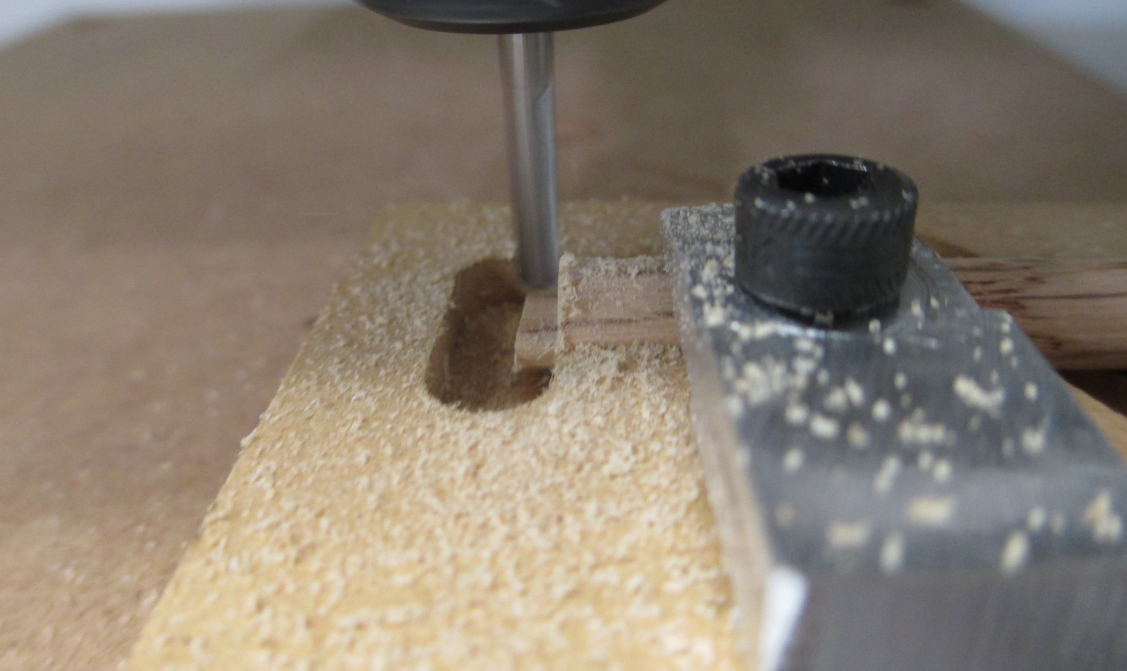
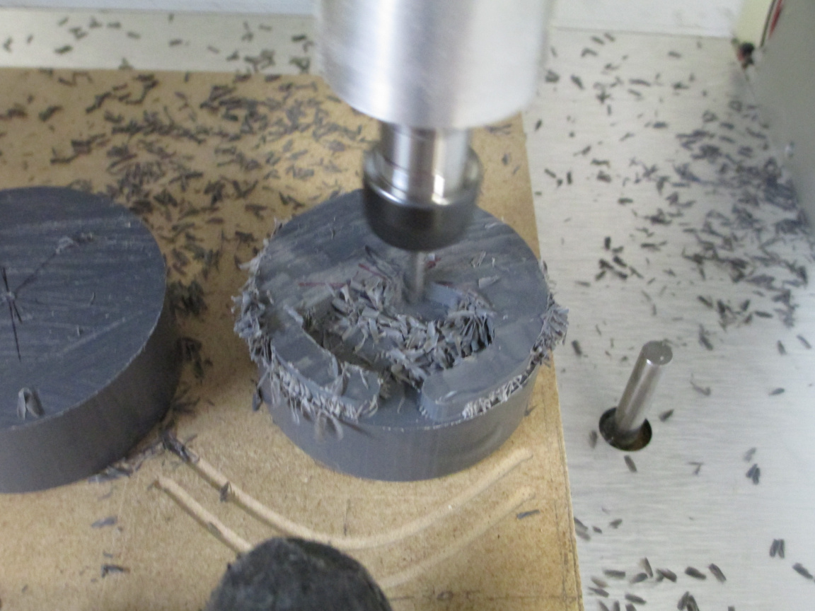
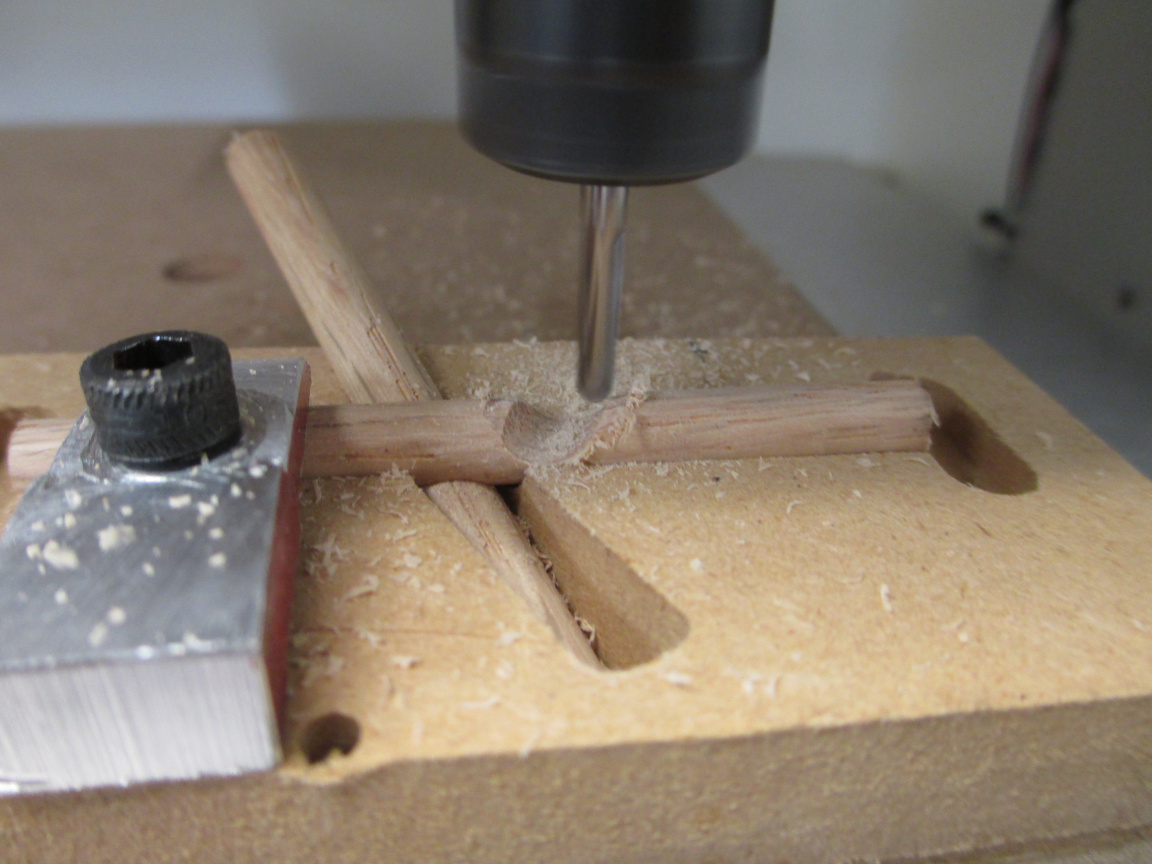
to get the rough-in
then finished uder the close supervision of the shop supervisor
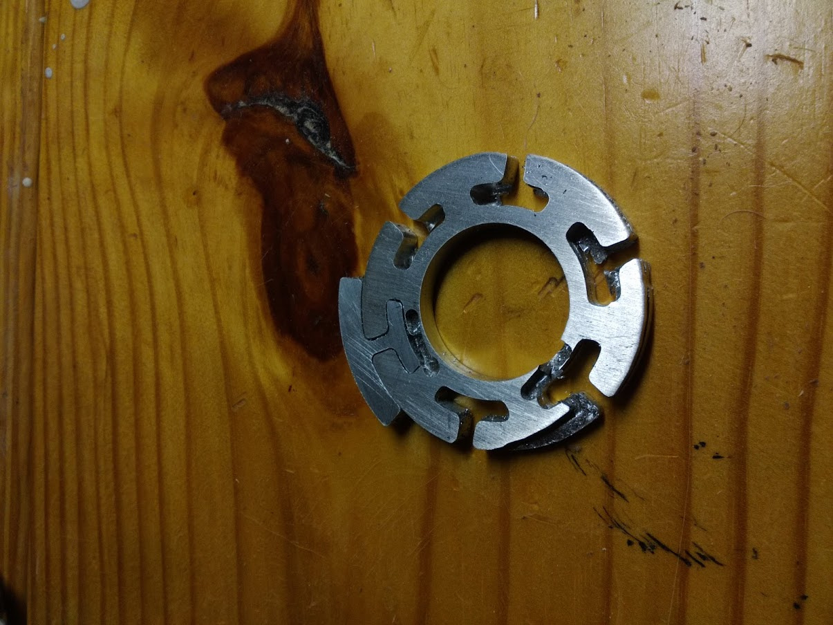
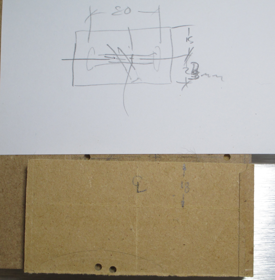
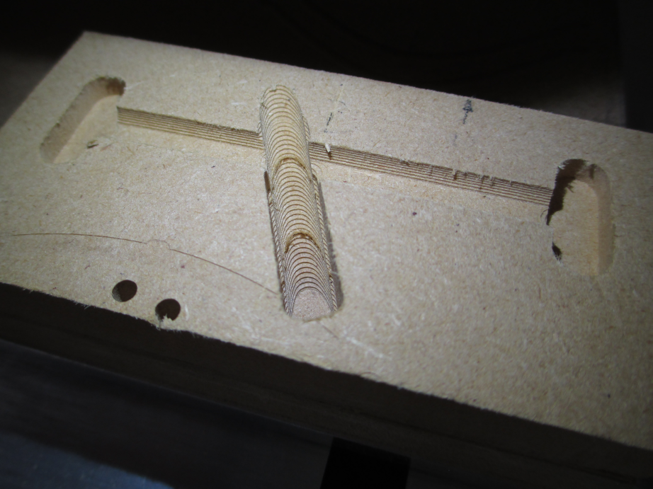
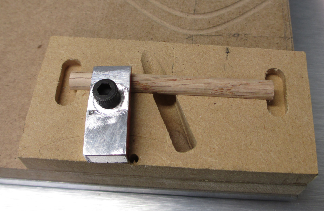
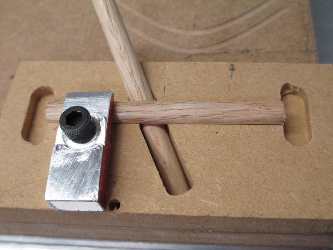
After finishing with the ball end, threading the hole for the hold down (you can thread MDF for machine screws. I usually get about 100 uses before the threads give out, by which time the fixture itself is usually done, too. MDF is not real rugged in this application, but it sure is easy) The first part was mounted
The clamp was made from a special work holding alloy known as “scrap bin aluminium bar” using the HWF process (Human With File).
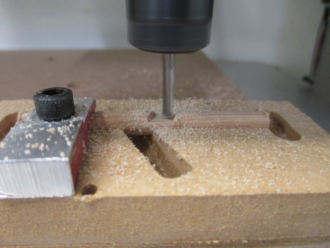
Cut to length
and notch
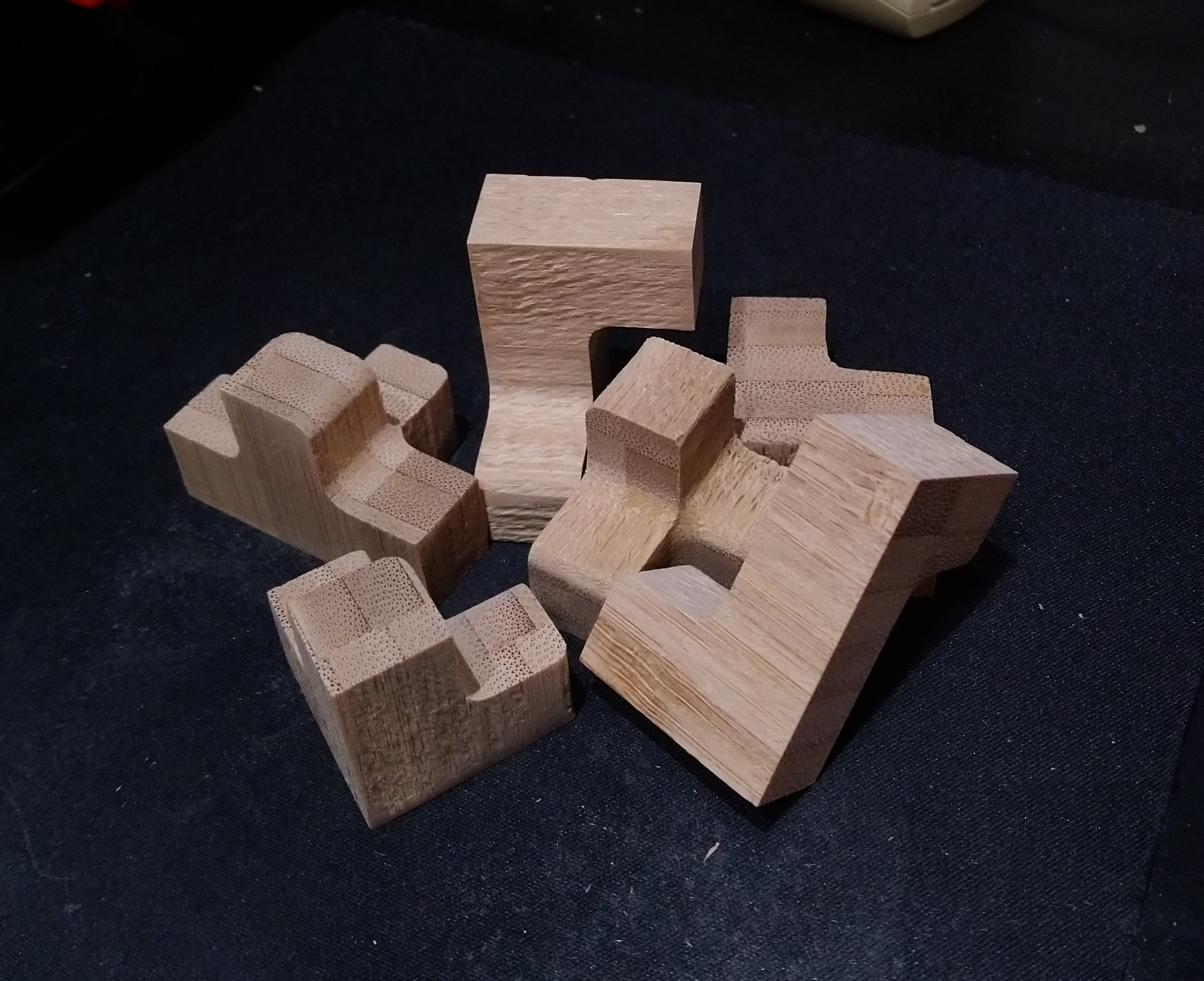
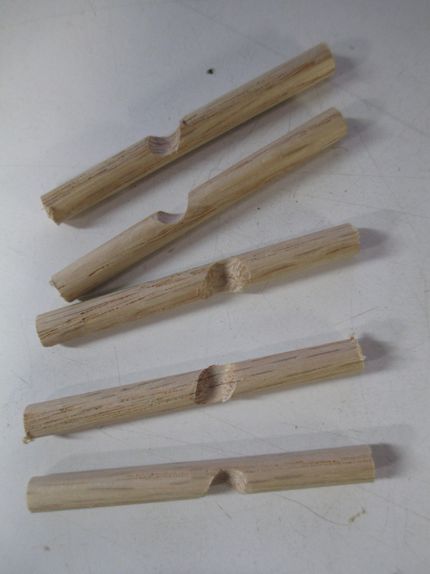
then repeat for all parts to get
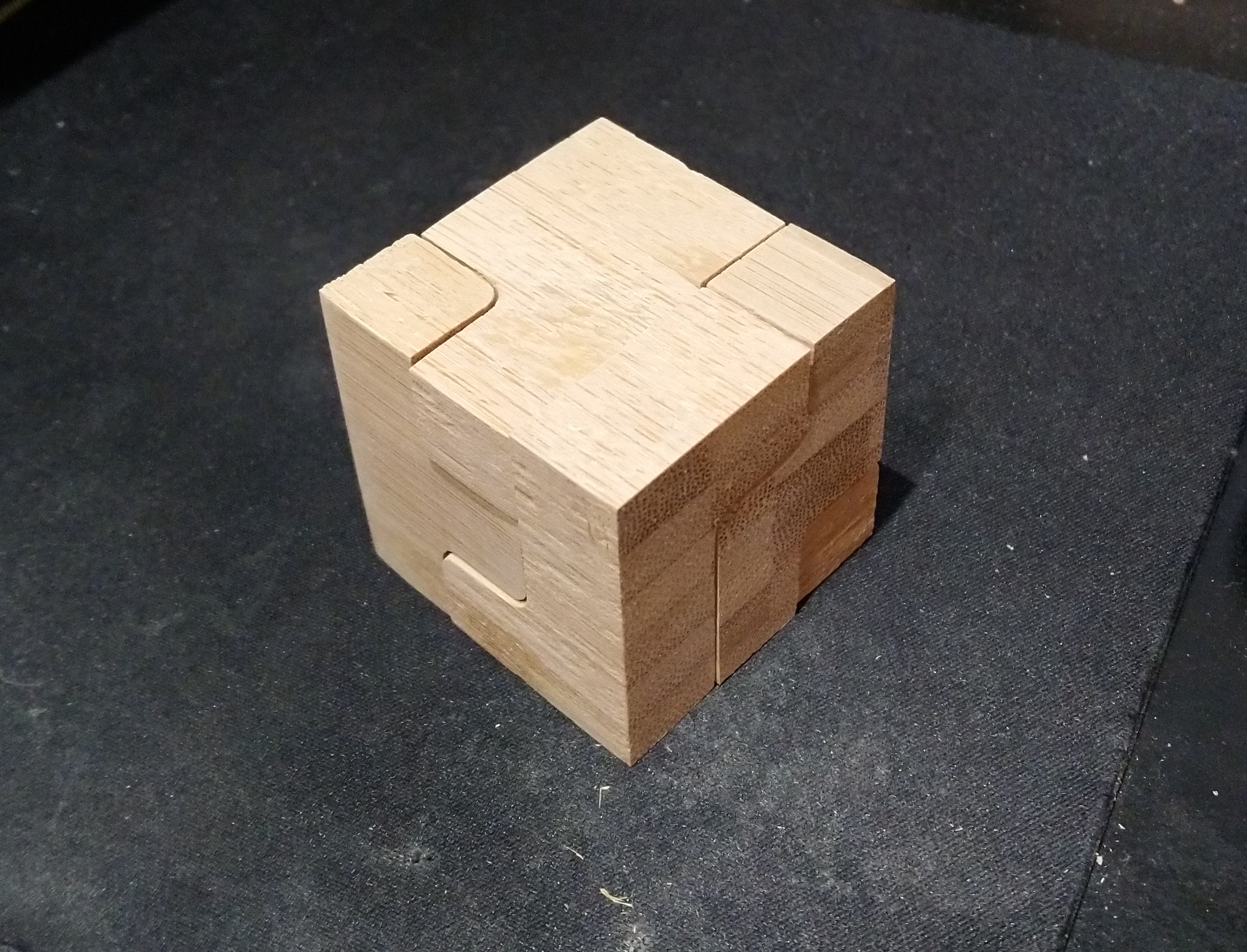
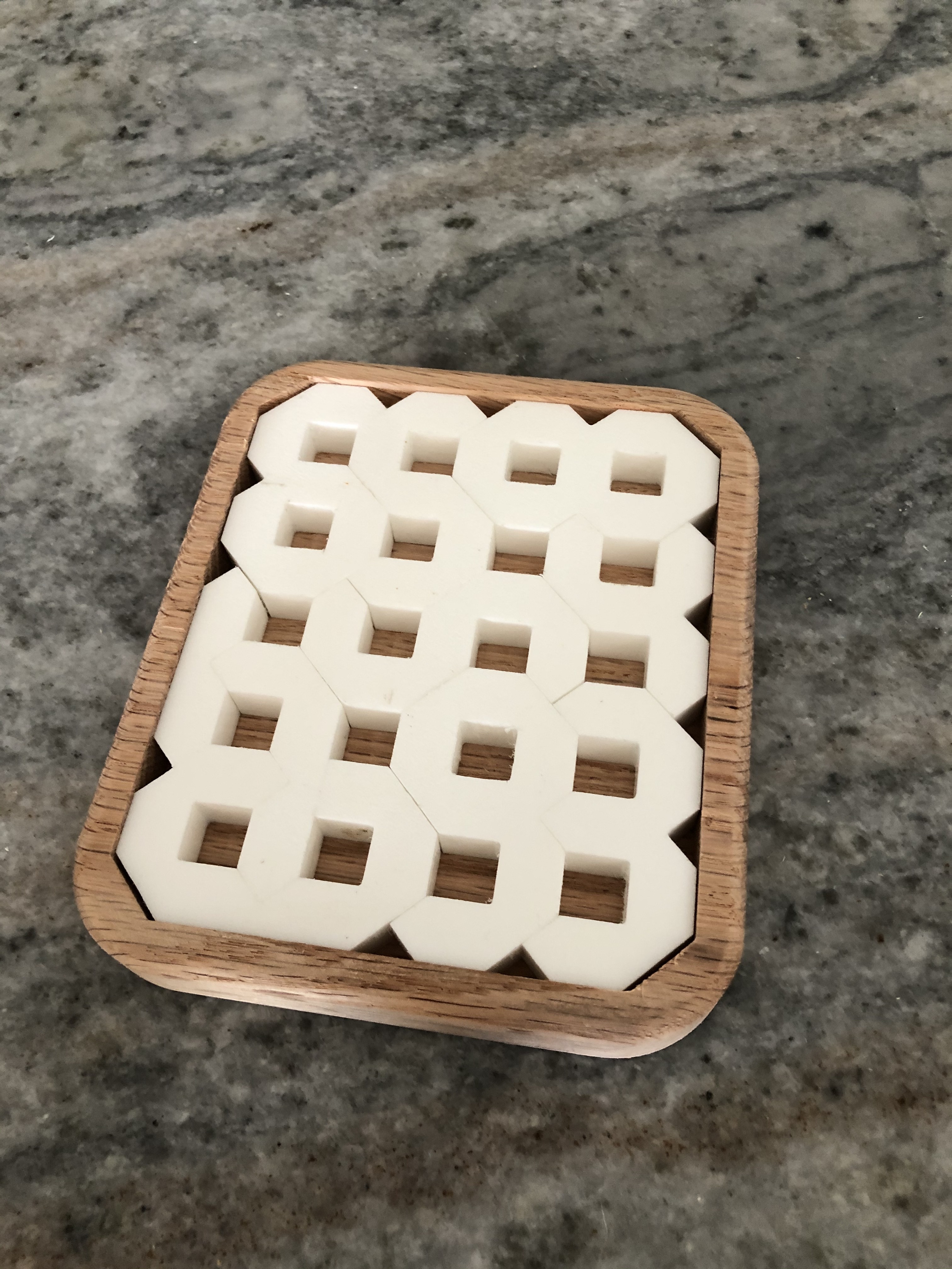
which is surprisingly difficult for most people to assemble to get
This is a puzzle as is, but not much of one. There is more to come, if I can find time this week to finish the next part between all of the zoom meetings and online training (that would take two hours total in person, though it will be maybe 15 to 20 this way). The CAD is done, but I need to CAM up and machine it.
EDIT: Part 2
Had some time this morning. Meeting cancelled.
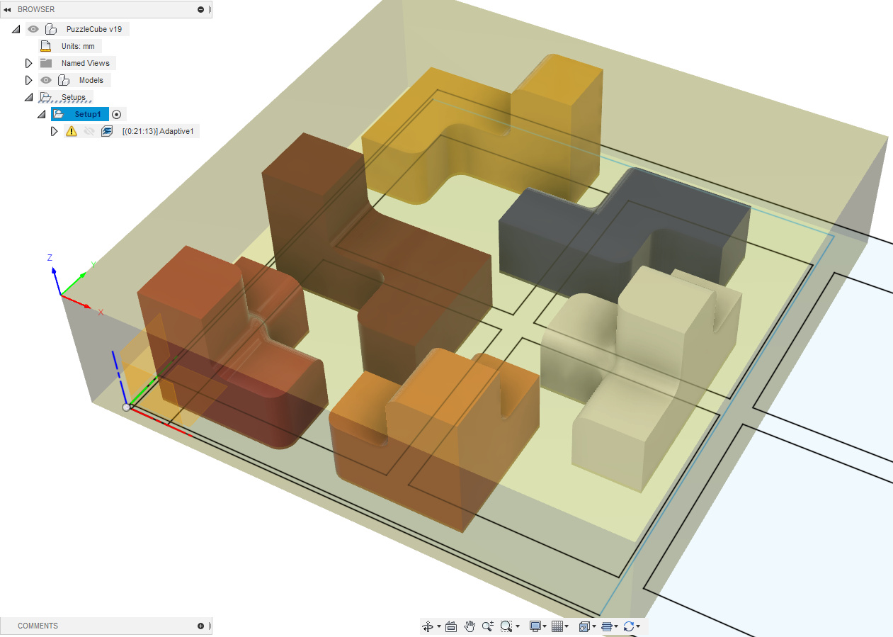
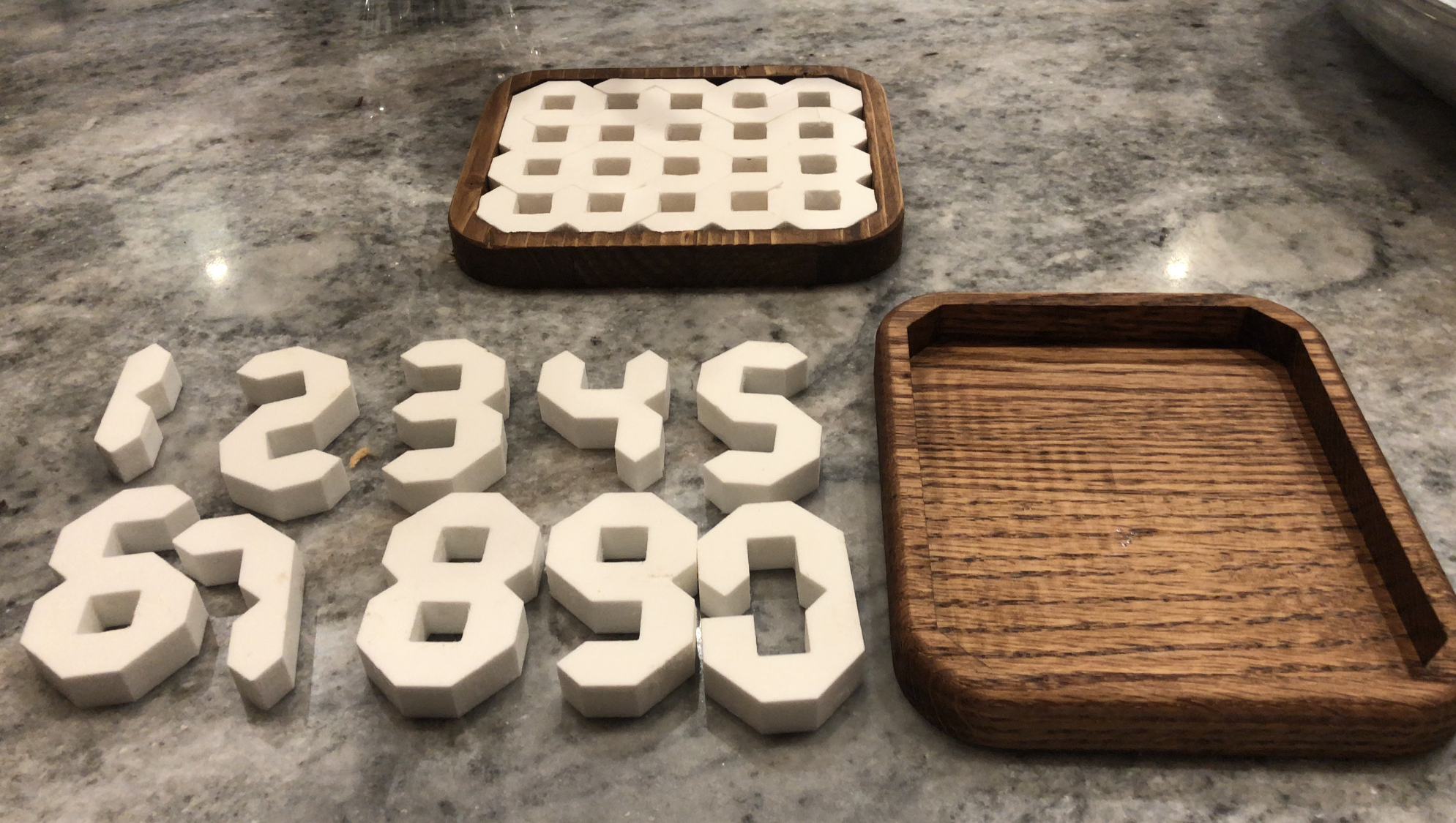
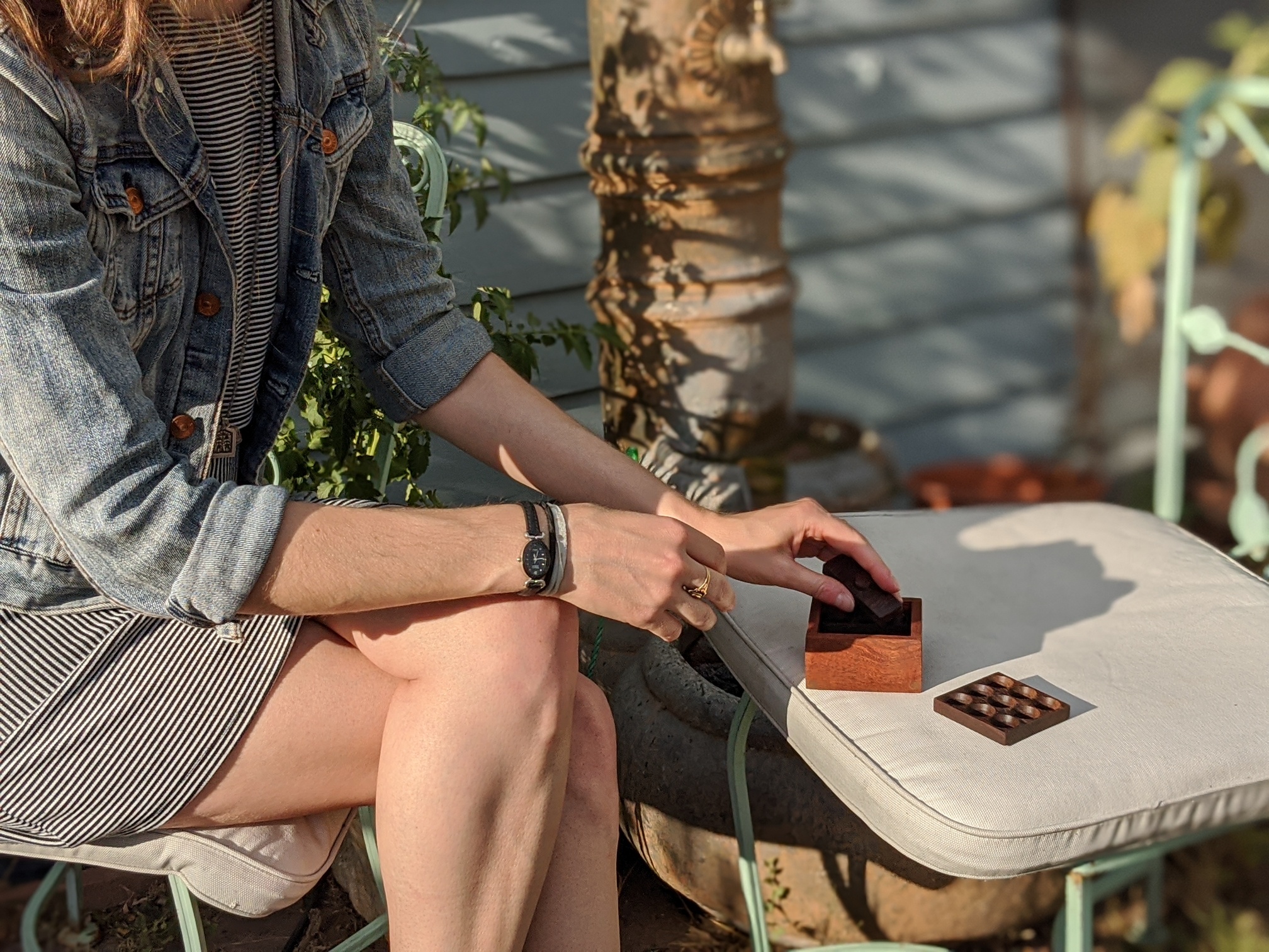
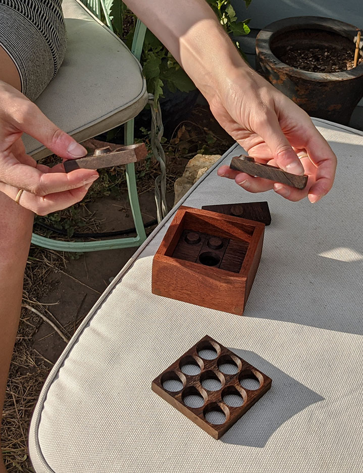
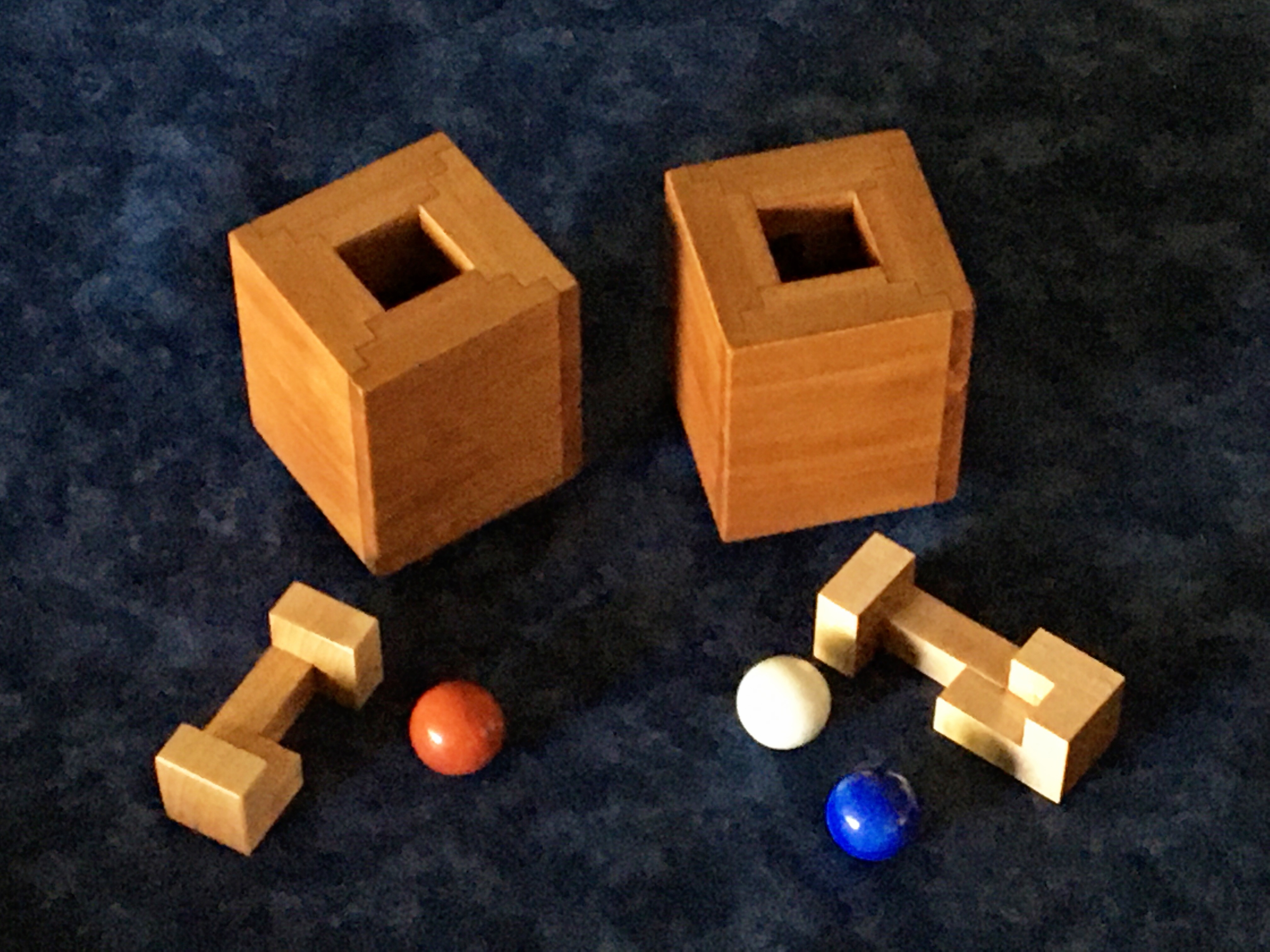
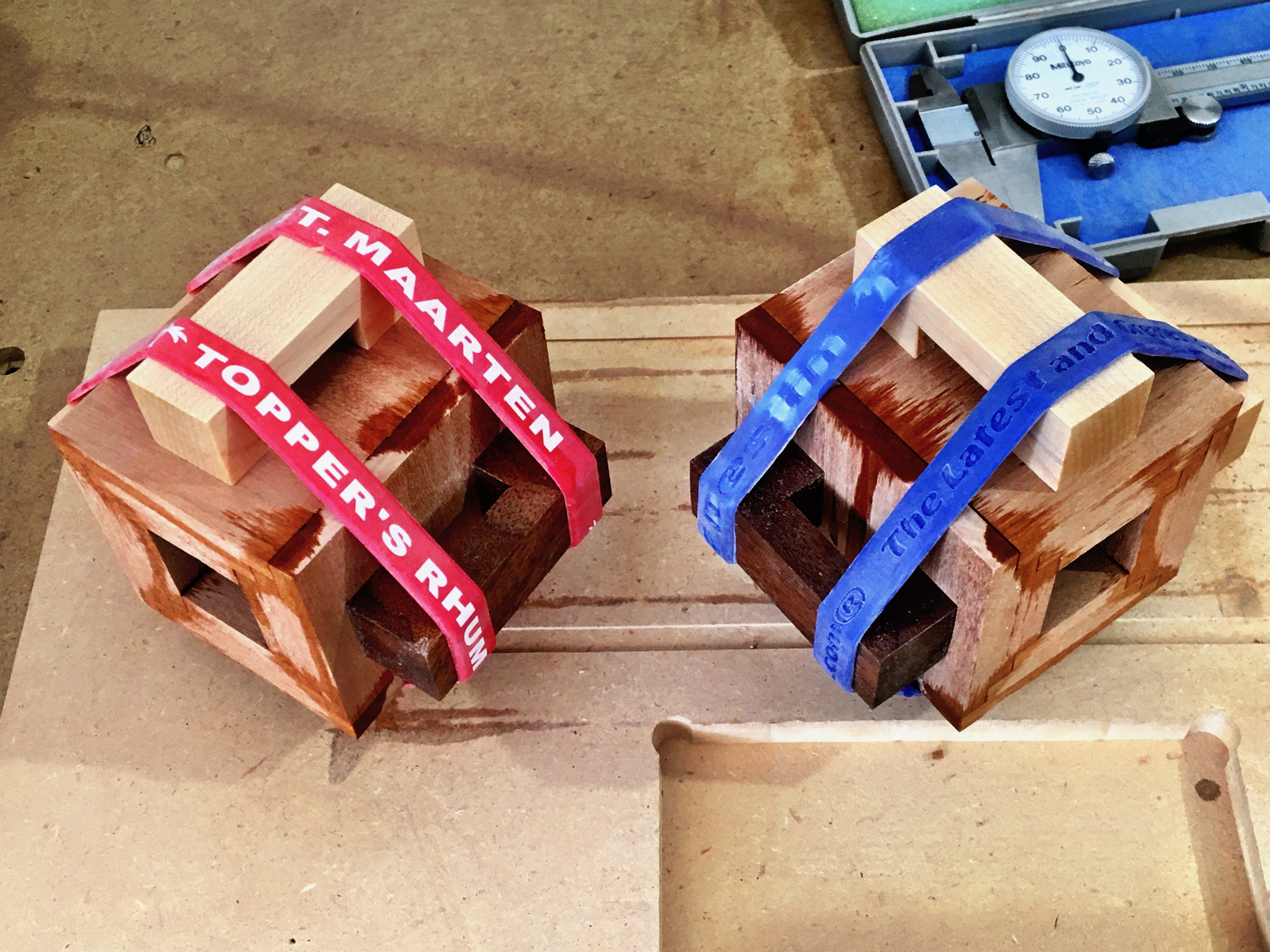
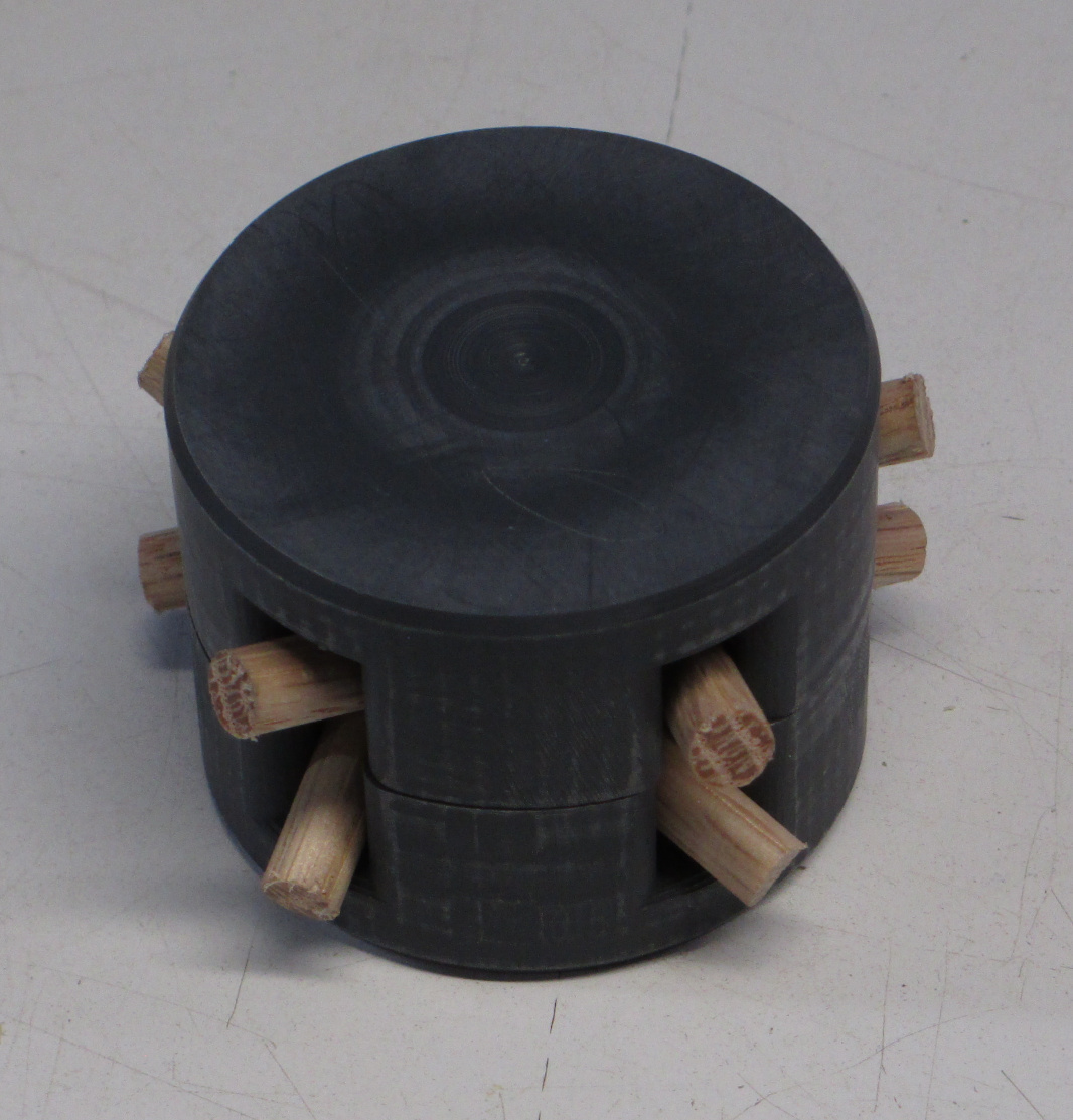
The actual puzzle is an assembly puzzle:
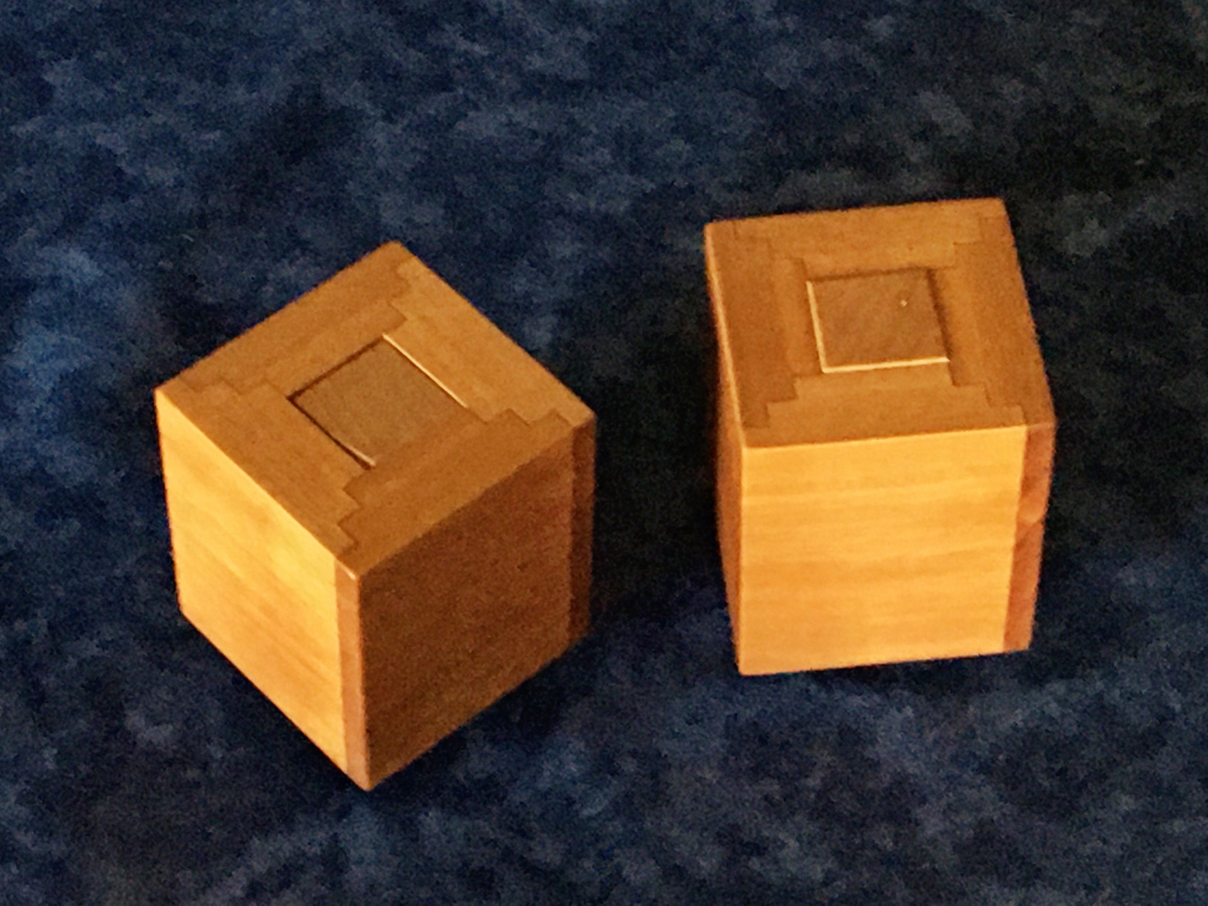
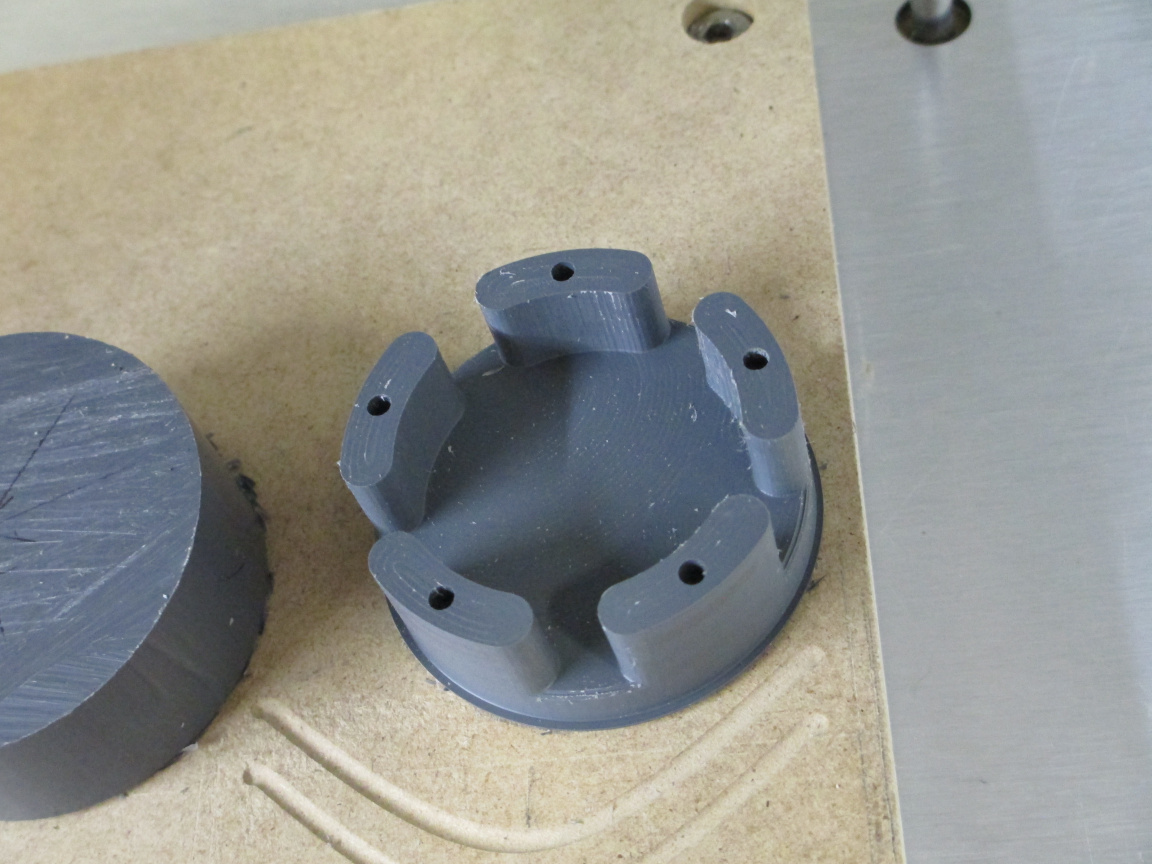
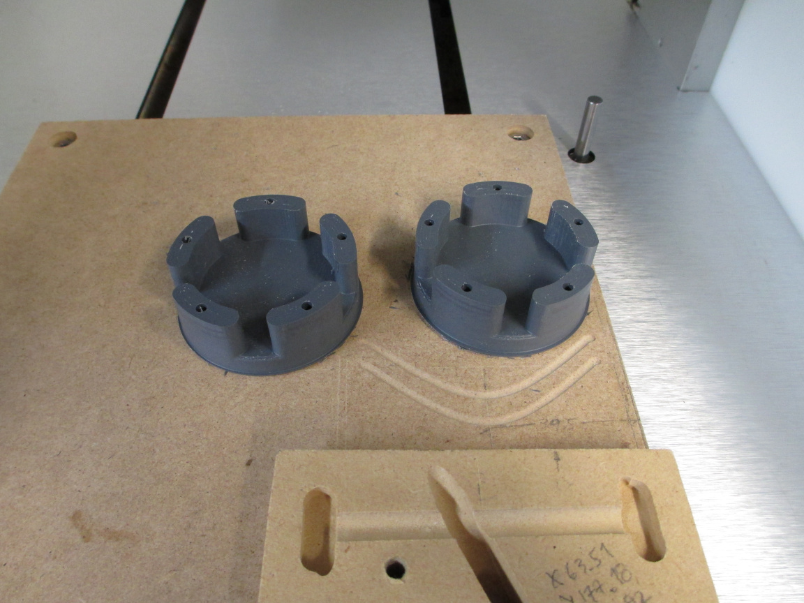
The five rods need to be assembled in the cage. The enclosure was machined in to identical parts, then assembled using dowel pins for alignment
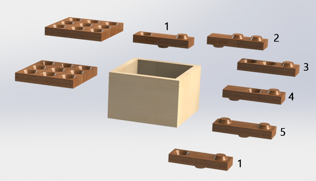
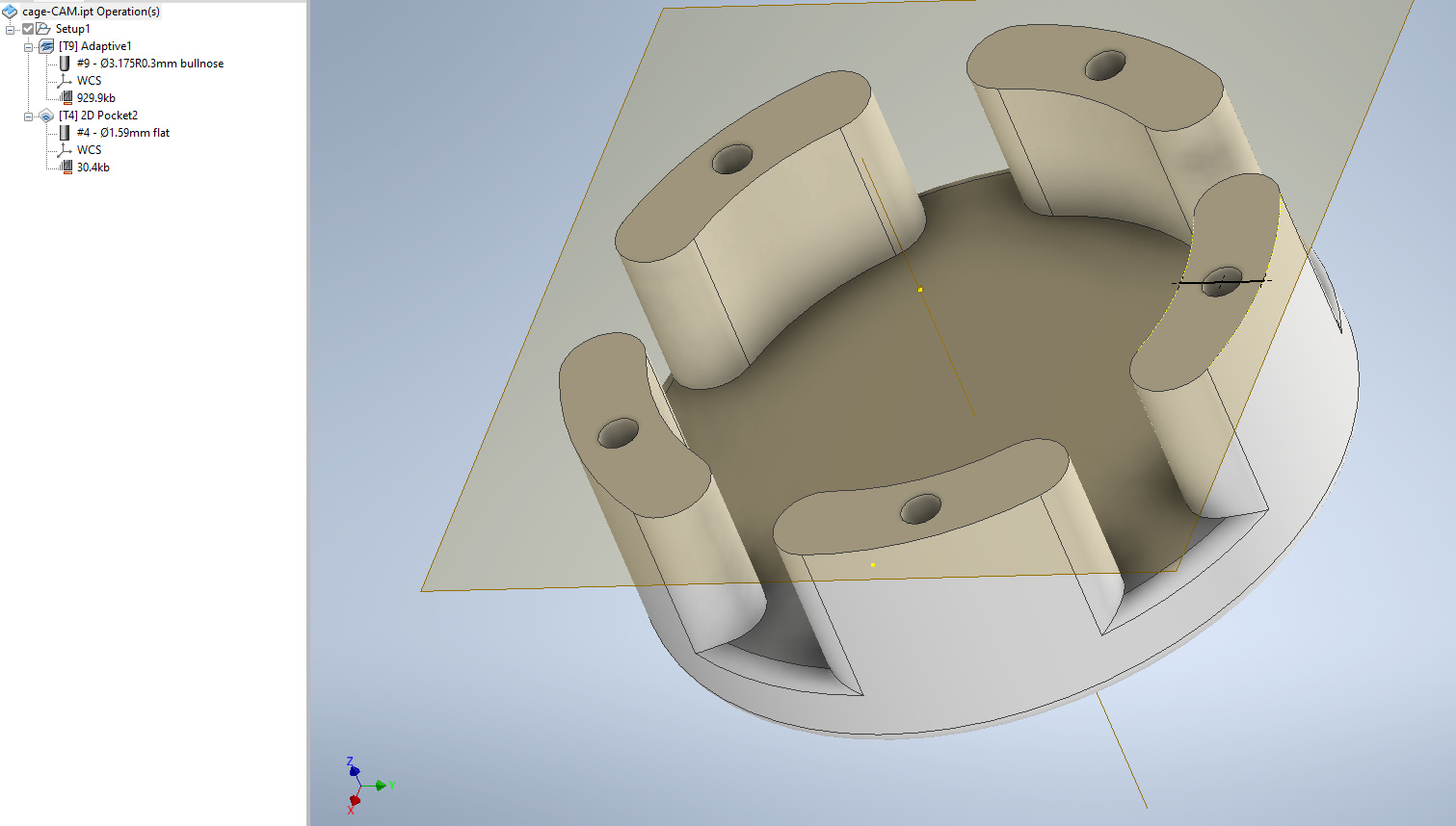
The model for each half
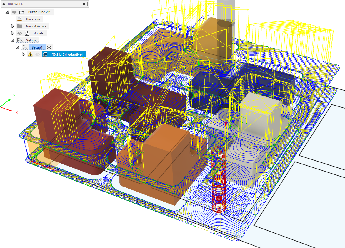
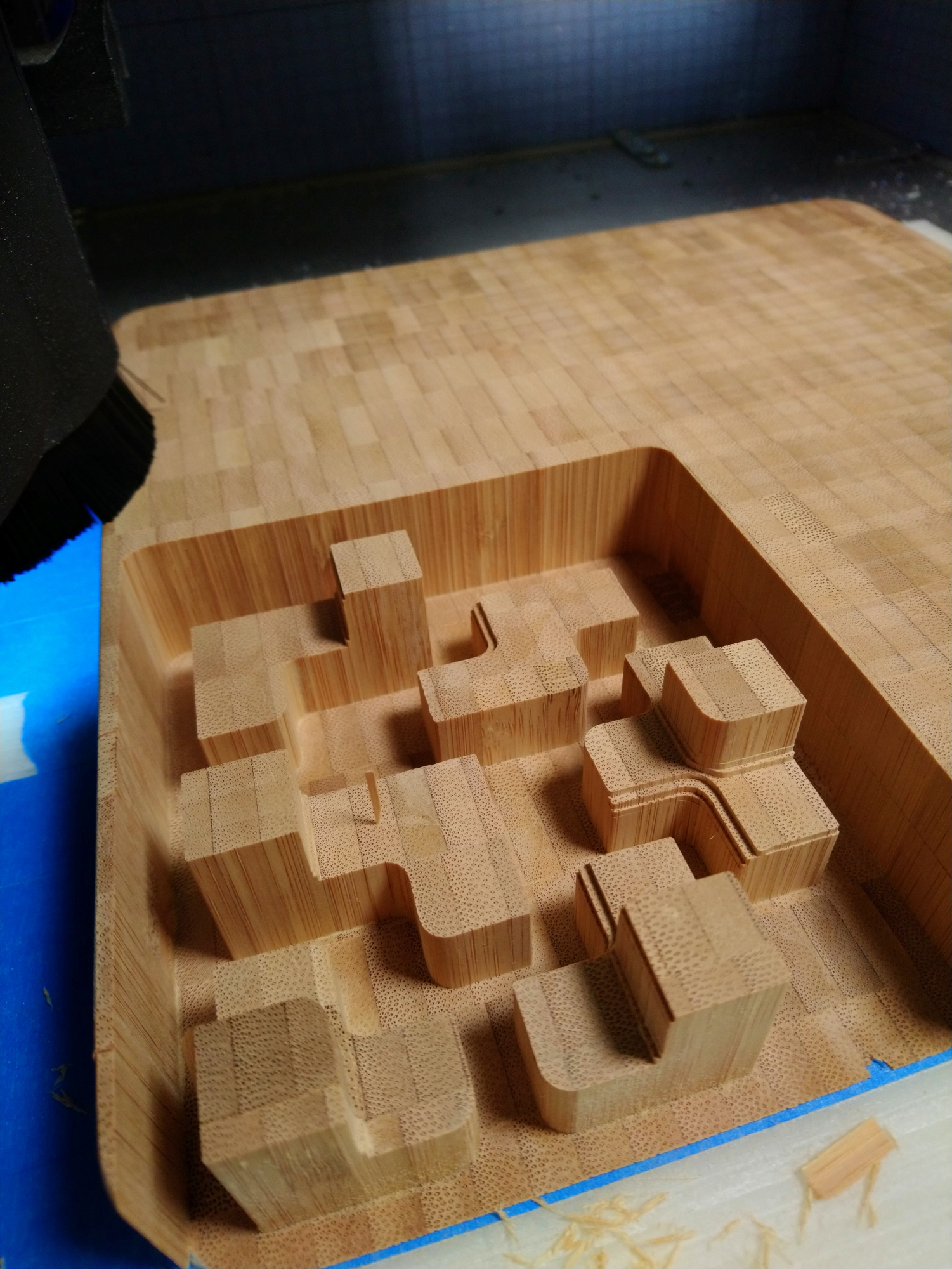
with both halves machined from PVC bar stock (because I had it on hand). The stock prep was done with handsaw, and then one end faced in the lathe to make a good surface to tape down. The machining was done with moderately aggressive parameters using a 3.2mm bull nose tool and a 1.6mm square end to bore the dowel holes. The 3.2mm tool was 1mm radial engagement at 5mm axial, 2000mm/min, 10Krpm. Nice chips
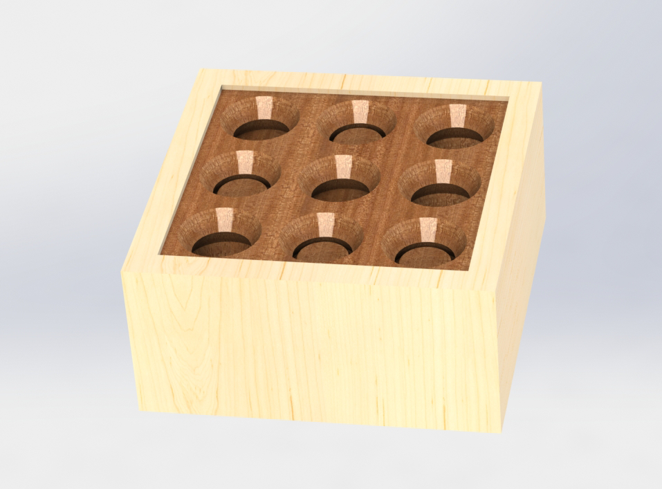
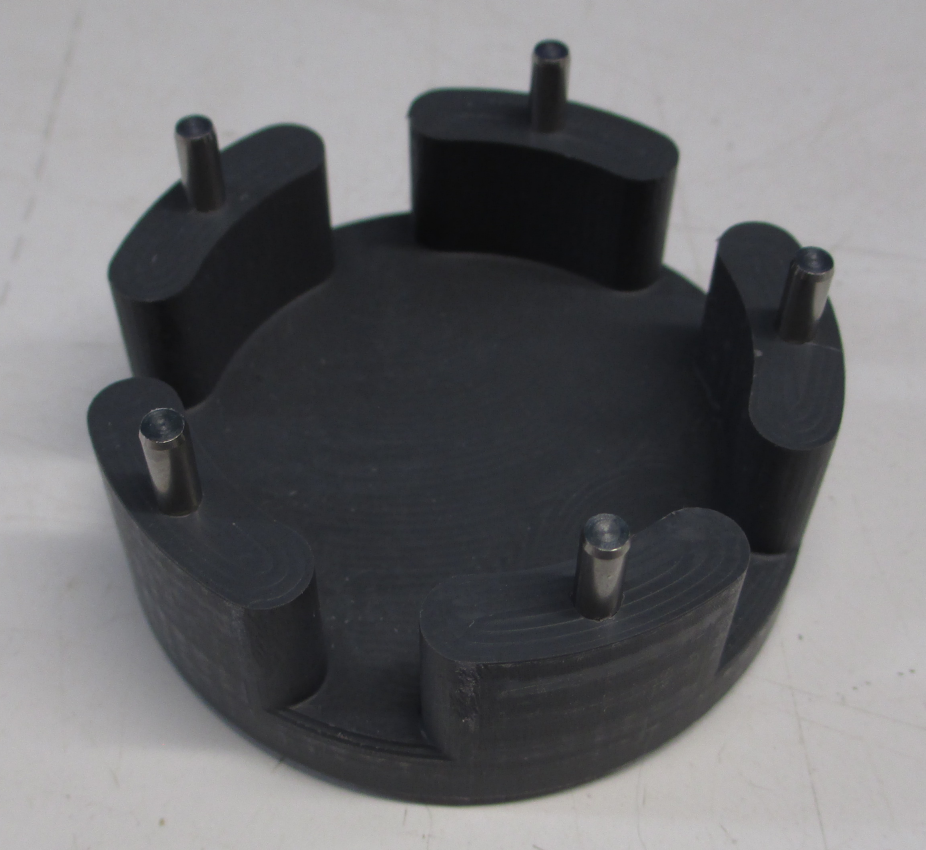
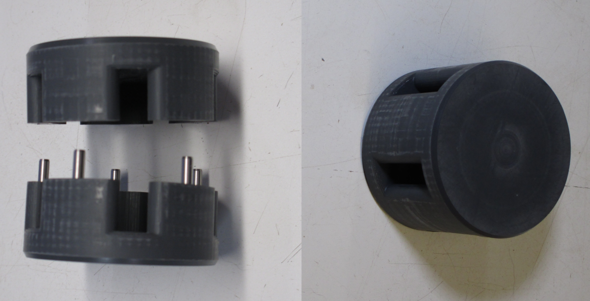
dowel pins in one part
then assembled
The puzzle is, of course,assembling the rods in the cage. I have left out one thing, to this point. As shown to this point, assembly is impossible. This leads to the nature of slight-of-hand.
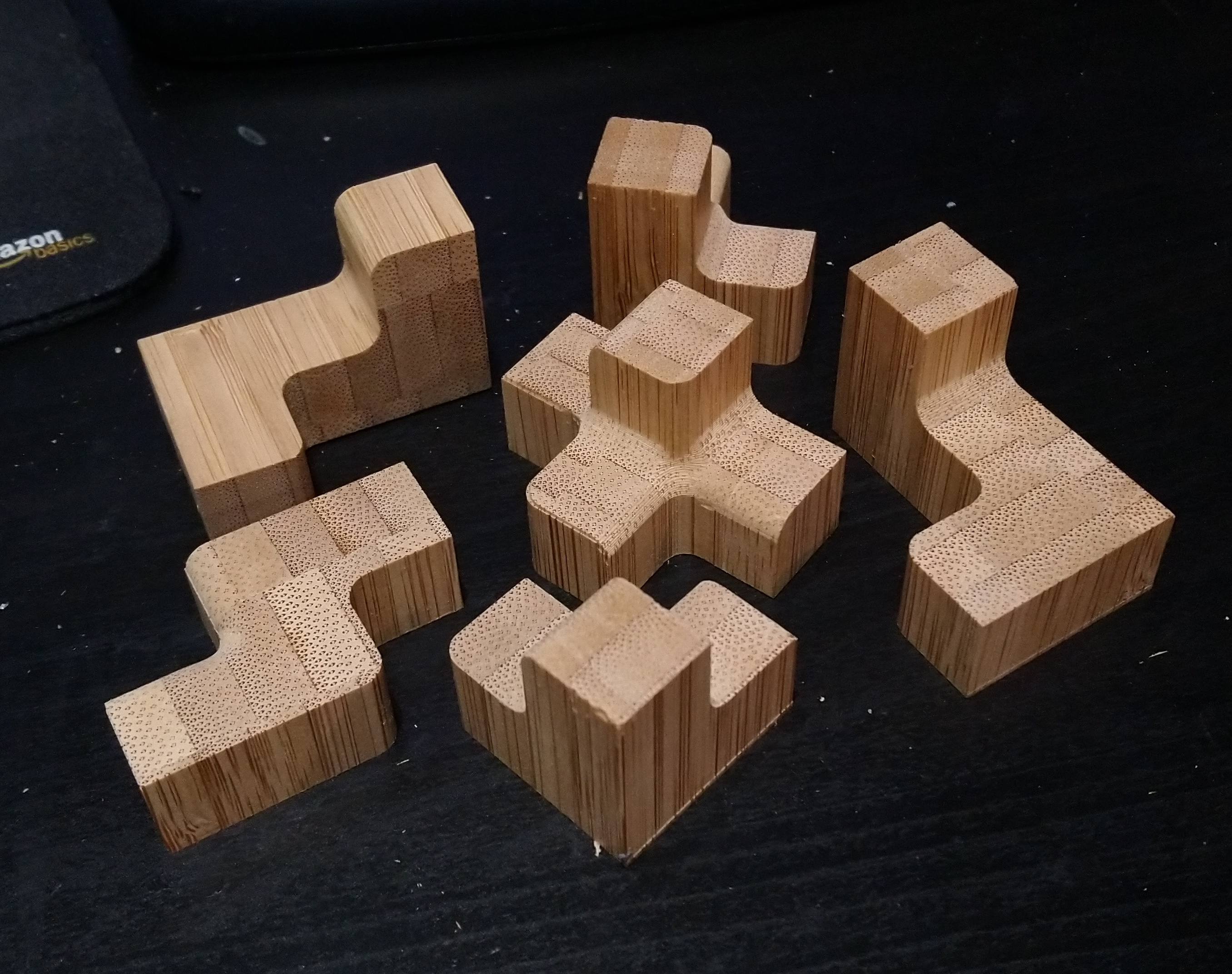
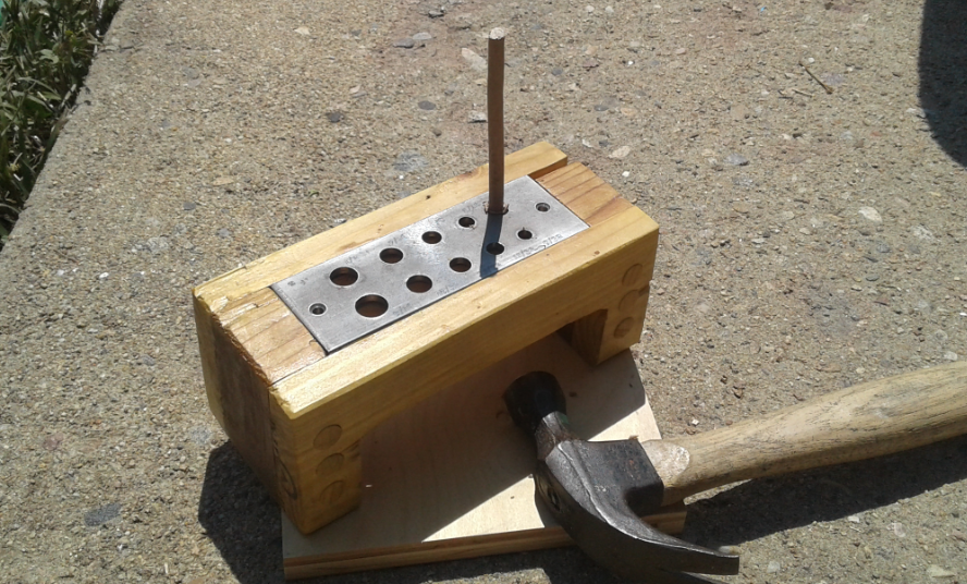
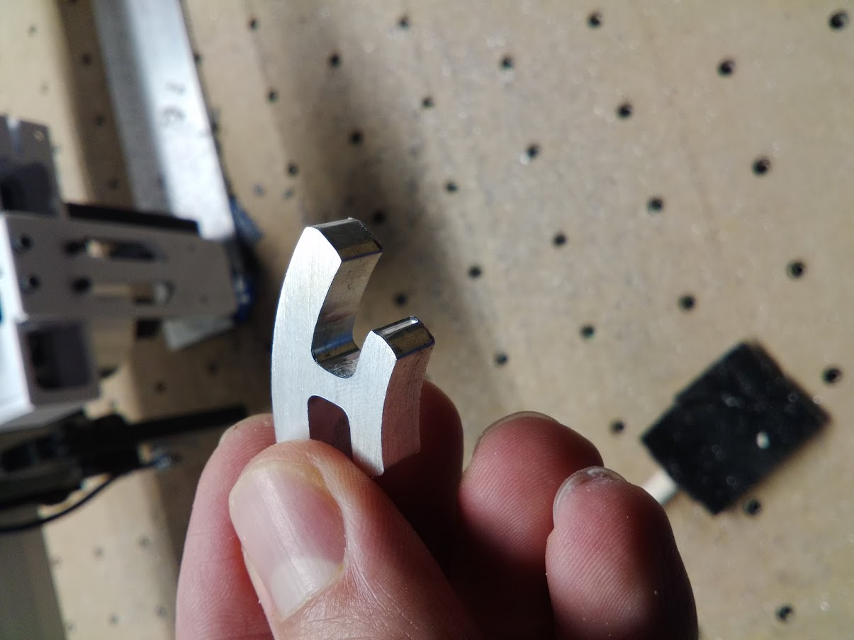
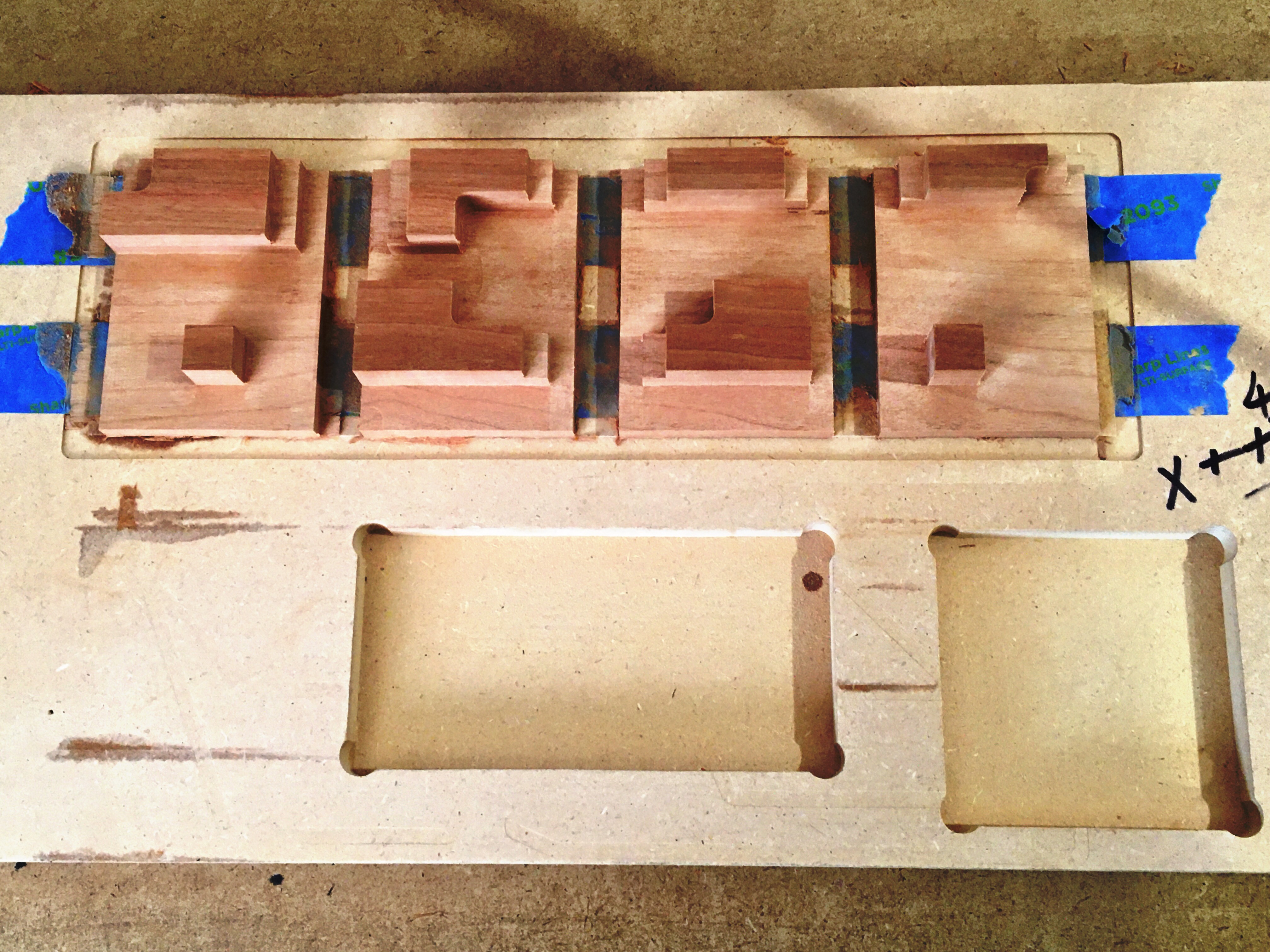
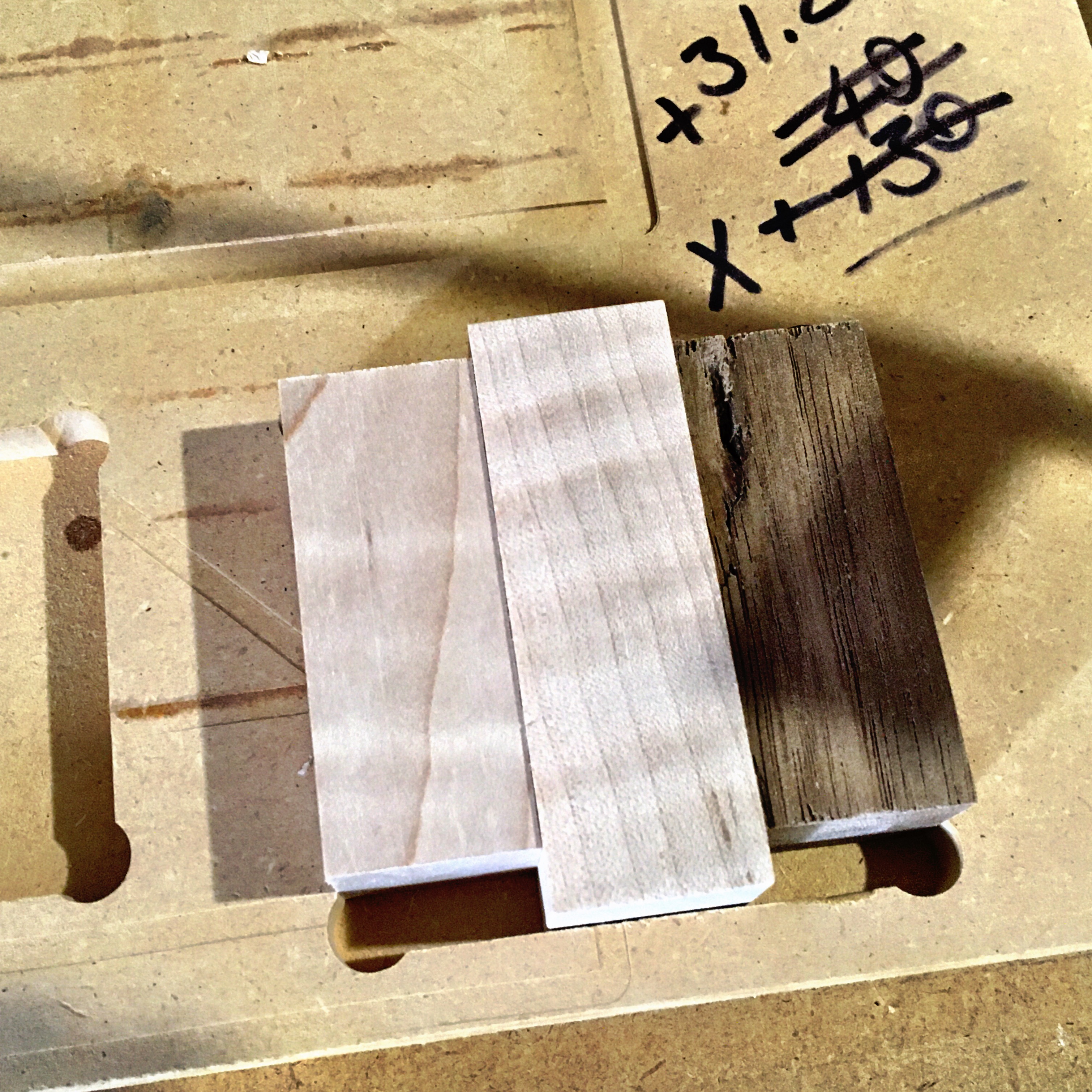
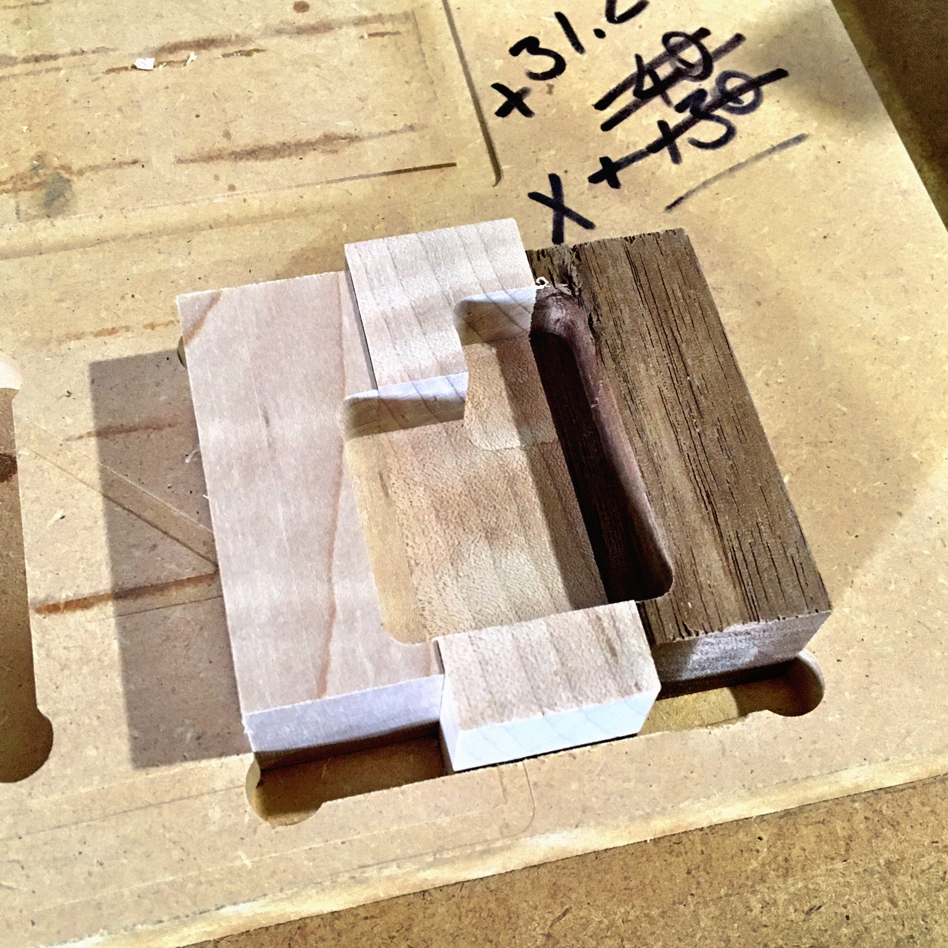
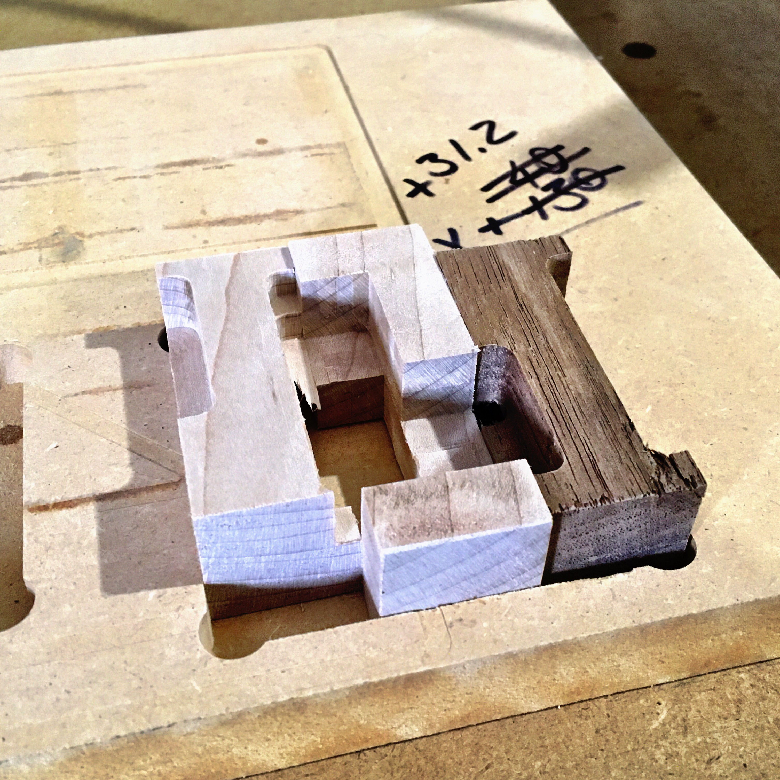
There are two more rods. One un-notched, the other with to notches, hence the fancy fixture:
The un-notched rod fits in the lower part of the fixture to position the other rod at the proper orientation for the second slot to be cut
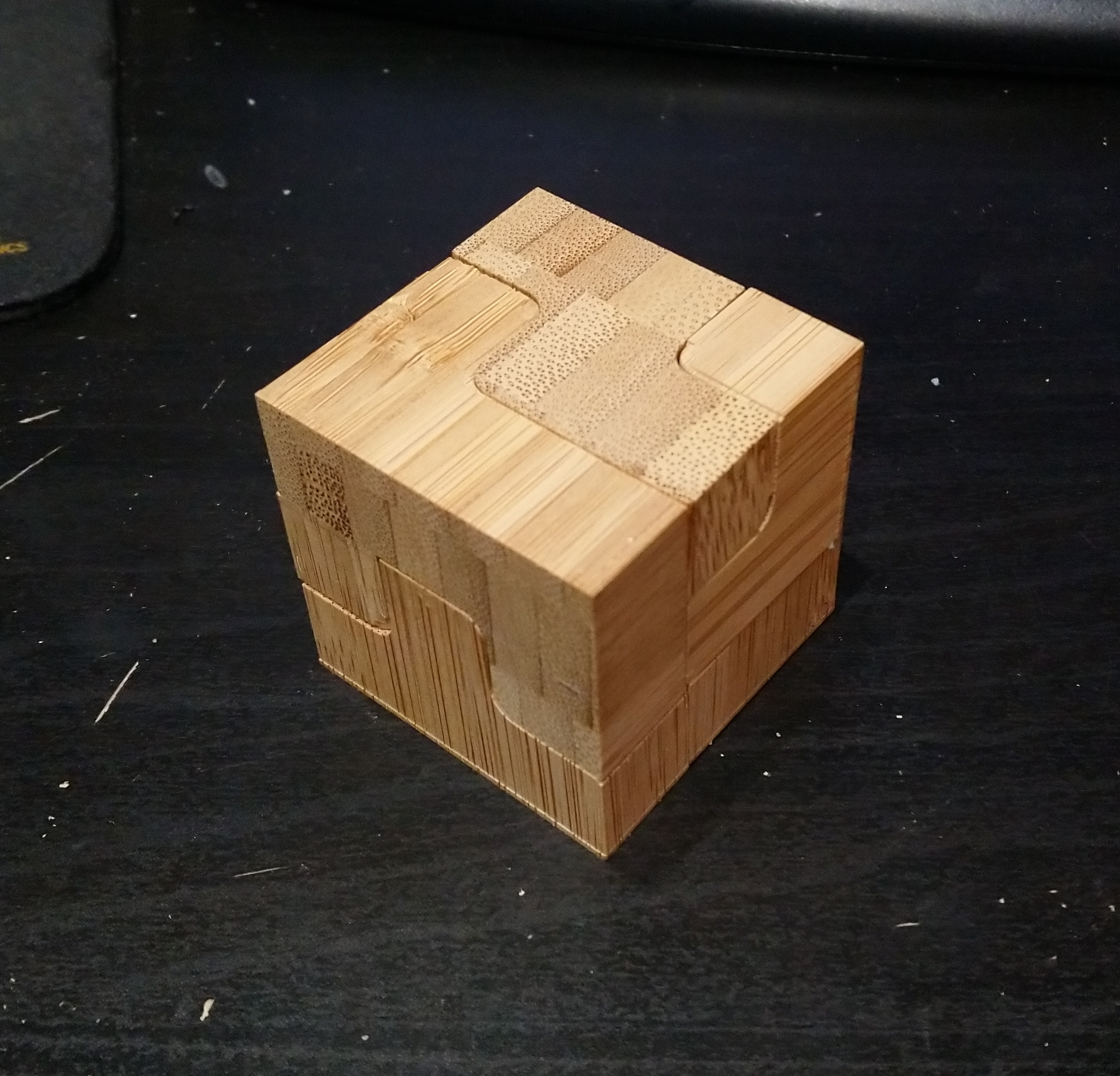
With these two rods, the puzzle can be assembled in the cage. The slight-of-hand?
Show the assembled puzzle to the victim. Disassemble, and palm the un-notched and twice-notched rods, replacing them with extra one notch rods.
When the victim can’t do it, show them, again swapping the rods.
(This is an old puzzle, I think Adams solve a version back in the day, as well as many Hong-Kong sources. I bought two to make a single magic trick. Only good one I ever designed myself)
The Inventor models (from my education license):
pentacage.zip (489.5 KB)
(this is the minimum model set to make the puzzle. There are about a dozen models total to construct it and develop the CAM. The cage model will need to be cut in half with a plane to machine, and your choice of alignment method added-separate pins like I used, fingers and holes machined in, whatever- as the model is the full cage.)