Can someone please recommend some videos on a tutorial of creating a step by step 3d carving…from start to finish? Good detailed ones please… not ridiculously short or vague or missing steps. Files would be a help too so I can follow from start to finish.
Preferred on Carbide Pro.
thanks for any help.
Can’t really help w/ videos. There are two at:
but not sure if they meet your requirements.
There is an overview at:
Overview at: Modeling Instructions - #6 by GJM
and we’ve worked up some step-by-step tutorials on various things:
What are you trying to do that you are having difficulty w/? If you’ll let us know, we can do a custom tutorial for it.
in my humble opinion, Carbide Create Pro “severely” lacks in 3D carving. While the video examples they are using are simple assuming you are cutting a full square or ‘regular’ shaped object, lets say your job is irregular?
Carbide Create Pro 3D needs the ability to select the image and do a relief boundary around the image. Otherwise you are wasting cutting time. Maybe there is a way and I just have not figured it out yet.
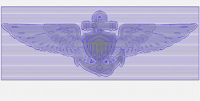
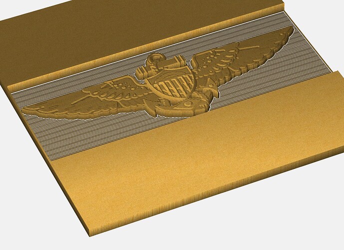
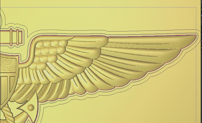
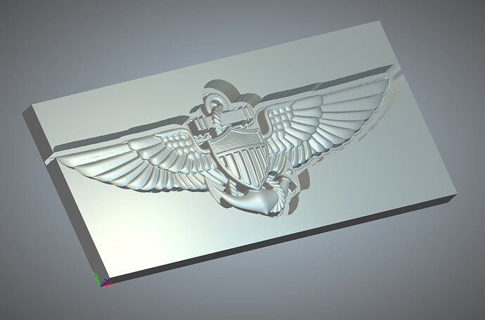
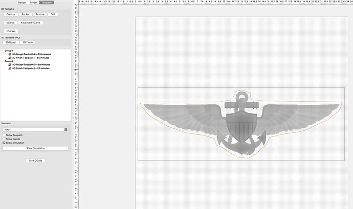
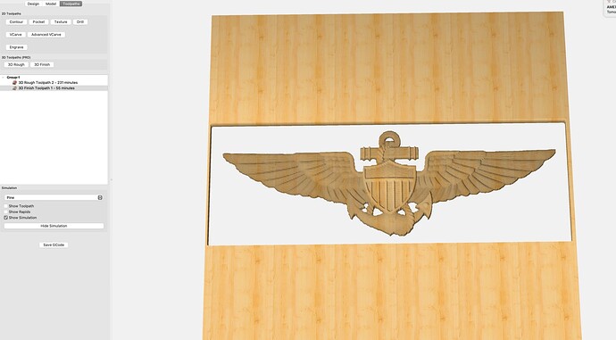
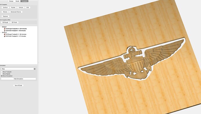
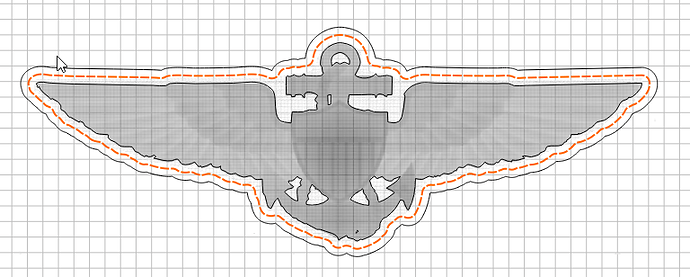
First two images are with Carbide Create. Last three are with Carveco. The cut time is almost in half because of the ability to create an offset relief boundary vector around image and cut jus to that.
Maybe there is a way and I just don’t know how to do it.
If you select a vector with the 3D toolpaths, they will act as a boundary for the toolpath.
That is the issue (or more of limitation) with 3d modeling in Carbide create. The greyscale image is non selectable and you can’t create a vector or select a vector off of the grey scale image. You have to create the vector as a rectangle in design view. As can see in photo, there is a lot of wasted cutting. If there was a way to select the actual image in design view or modeling view, and create an offset of the image by .25, then we wouldn’t be cutting out all that negative waste in the corners. And the offset will still allow enough room for toolpath to clear.
I had to hand draw a makeshift offset vector around the wings, and look at the difference in milling time. It would just would be easier if the greyscale model was selectable to make an offset quicker. I’m not smart and still learning carbide create software and using greyscale vs .stl models.
We’ll see if we can make that easier in V7
That be awesome. Greyscale vs stl modeling is new to me and I’m sure it’s not an easy programming change for you all.
Andrew, sorry felt bad for highjacking your post.
I was in your spot a few weeks ago. The hardest part for me, was getting a greyscale heigh image. I previously used a different software package and worked exclusively with stl model images.
Carbide is greyscale and all my models are stl. So, as a Mac user, I either use Gimp to create image and convert to greyscale, or blender. Both are free. Other way is to use website that converts stl to greyscale. STL2PNG - javascript edition
Once you have the greyscale image it is actually a very easy workflow process after that. The two videos that William posted are actually very good.
- Job setup parameters.
- Under model tab, import image and scale to size. The videos helps with understanding settings as height and base height.
- Have to create a vector back in design view. This is the important step that took me a while to learn and understand in carbide create.
- Toolpaths, select the vector and set roughing and detail tool paths.
Biggest thing to remember is nothing works unless you get that vector in design view.
Jim, I didn’t have a good greyscale so I just captured your image above & cleaned it up a bit.
I imported the image in 3D (Model). Then I used Trace Image with a high threshold to get the outline & then offset it. It was pretty quick.
A little tricky to scale the trace to match the model. But the nice thing is it gives you the overall height & width, so you can measure the model, and then just enter the same dimension when scaling the vector.


