Today I played a bit with taking STL files into Carbide Create (PRO).
This is a work in progress, but the question comes up here often enough that I figured I should show screenshots of what this process looks like
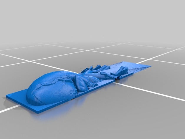
Step 1: Find a suitable STL file
Not all STL files you can find on the internet are suitable for machining on your Shapeoko. 3D printers can print “true 3D” objects that contain hollow areas underneath solid areas. With the Shapeoko, you can only “cut from the top”, so the hollow areas are out of reach. But eve with this limitation, you can find many great STL files on thingiverse, etsy or ebay.
For this tutorial, I’m using the STL file from https://www.thingiverse.com/thing:3260660
Step 2: Convert the STL file to a height map PNG
Using the tool from https://github.com/fenrus75/FenrusCNCtools I converted the STL file to a heightmap grayscale PNG:
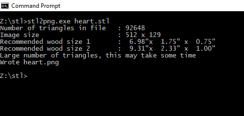
This creates the following heightmap PNG:

Step 3: Use the Modeling feature in Carbide Create (PRO) to create an appropriately sized design
- Set the size of the stock to the recommended size
- Create a rectangle around the whole piece
- In the model view, import the PNG (see screenshot)

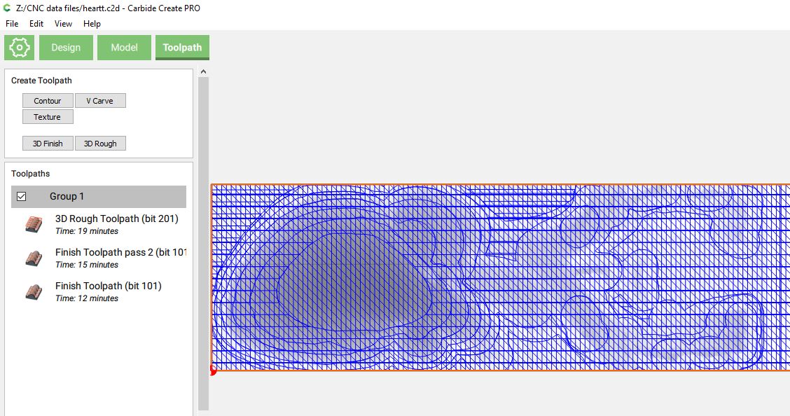
Step 4: Create toolpaths
Generally I create 1 roughing toolpath and 2 finishing passes at different angles:
Step 5: Check the simulation
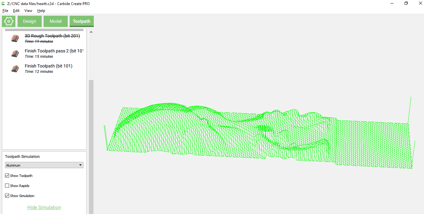
(the unstable release 433 from yesterday has a visualization bug in this preview)
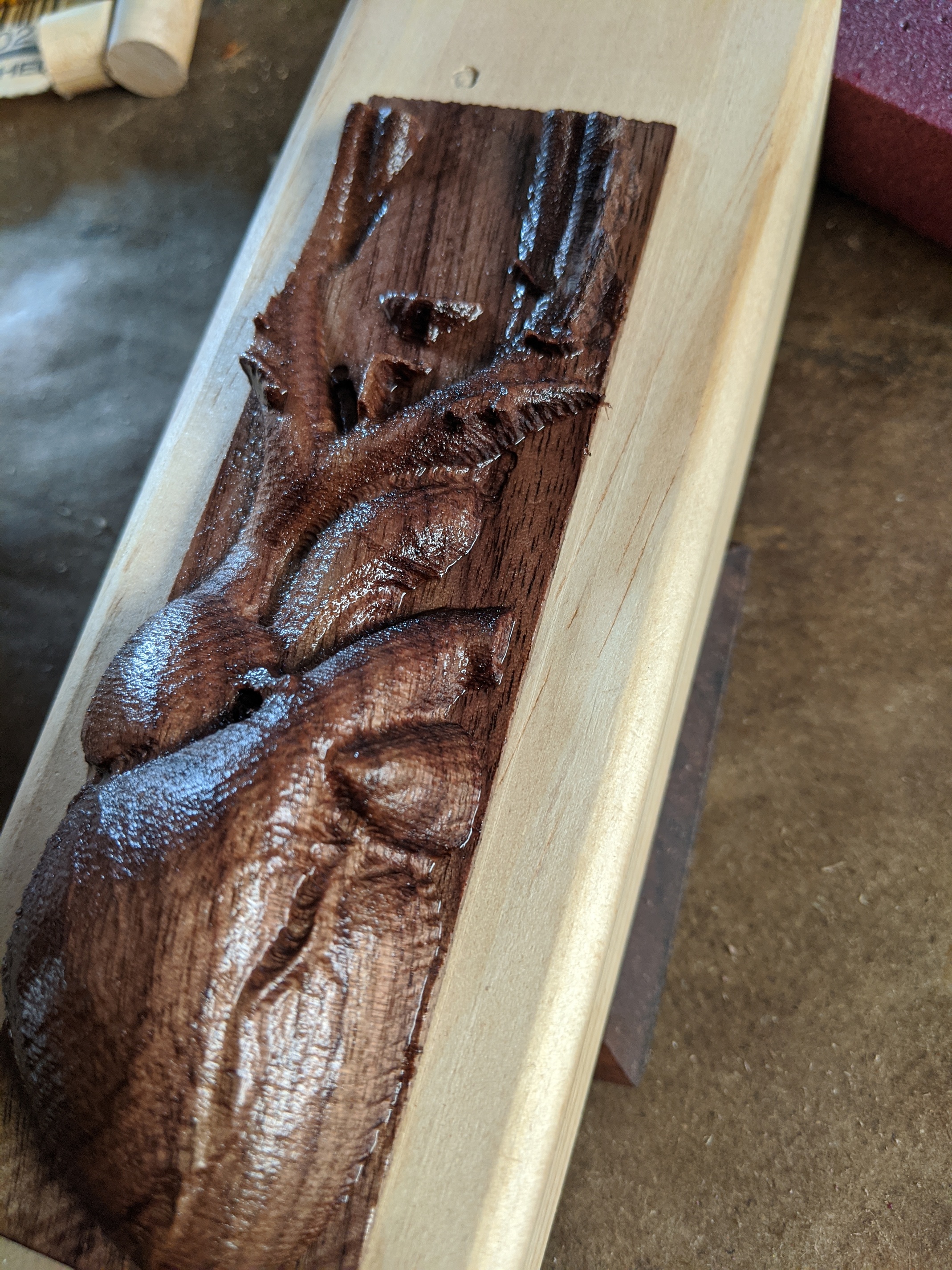
Step 6: Export to GCODE and cut the wood
… we all know how this works …
The C2D file is here: heartt.c2d (678.3 KB)