I’m using Solidworks to create in. I’m trying to do a single curved cut on a 2x4 for an arbor.
So far, I cannot export a single line from Solidworks to Carbide Create , cannot create that curve in Carbide Create, and in all cases Carbide Create seems to require a closed loop cutting path.
How do I make a singe curved cut along 1 face?
This would be so easy to do by writing g-code directly into the machine (<100 lines), I don’t know why it’s so complicated.
If you have a 3D CAD package, why not use a 3D CAM tool?
Either Carbide Create Pro:
or MeshCAM?
Just export an STL and be done w/ it.
Note that writing G-code in Grbl is not that easy/pleasant — there are no variables, loops, or any sort of branching, it’s an exercise in tedium (I’ve done it), alternately c.f.,
and FWIW, I’ve been working on:
That said, I often fall back on techniques such as:
or
If you’re still stuck, upload an STL and we can look into it w/ you.
Is it a 3D shape you need to export?
If not, SW can export dxf from a face, sketch, drawing or flat pattern.
CC can import .c2d, .dxf, .svg
Can you show the sketch or drawing?
I have no intention of buying any more cad programs to further this project since I’m already familiar with SW, but if I have to I will.
I’ll look into MeshCAM and the other links as soon I can (I hadn’t heard of it before, thanks)
I too have had classes (11 years ago) on writing gcode (pain in the bleep).
I’m a little skittish about sending an stl directly to CM without testing it in CC first as this is my first time running this cnc (scared of crashing).
Importing a dxf file to Carbide Create without a closed loop always ends with:
Import Warning
The imported file contains open vectors, which are not suitable for use with V-Carve and Pocket toolpaths.
Use the join command to try to close/merge these vectors.
Which is a dead end and why I’m here.
ArborPart1.DXF (21.4 KB)
ArborPart.DXF (21.2 KB)
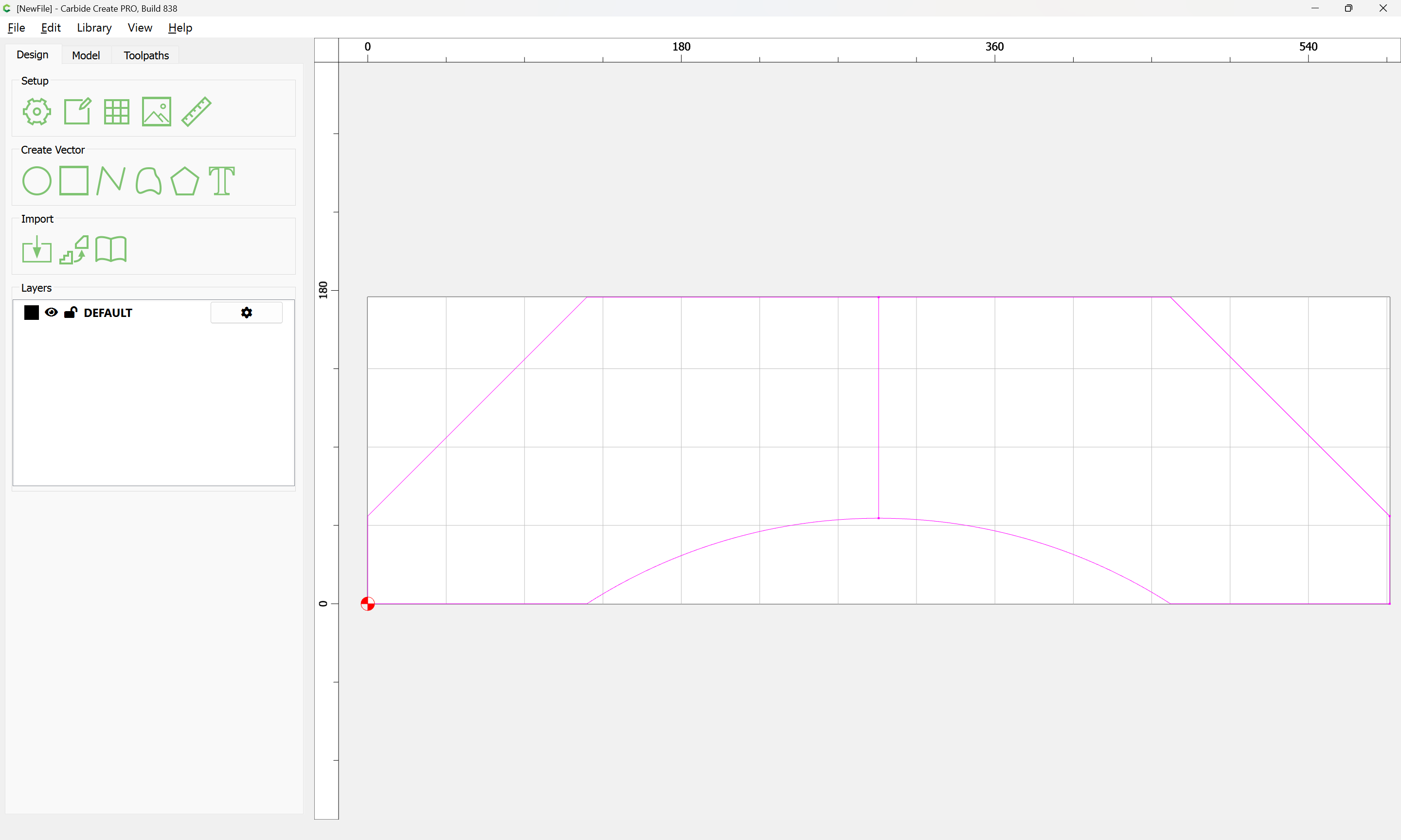
ArborPart.dxf imported as expected:
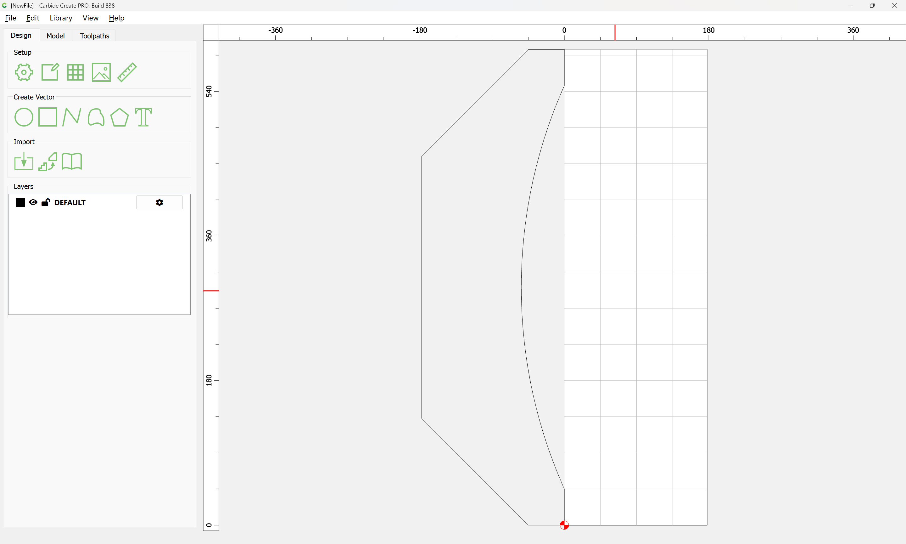
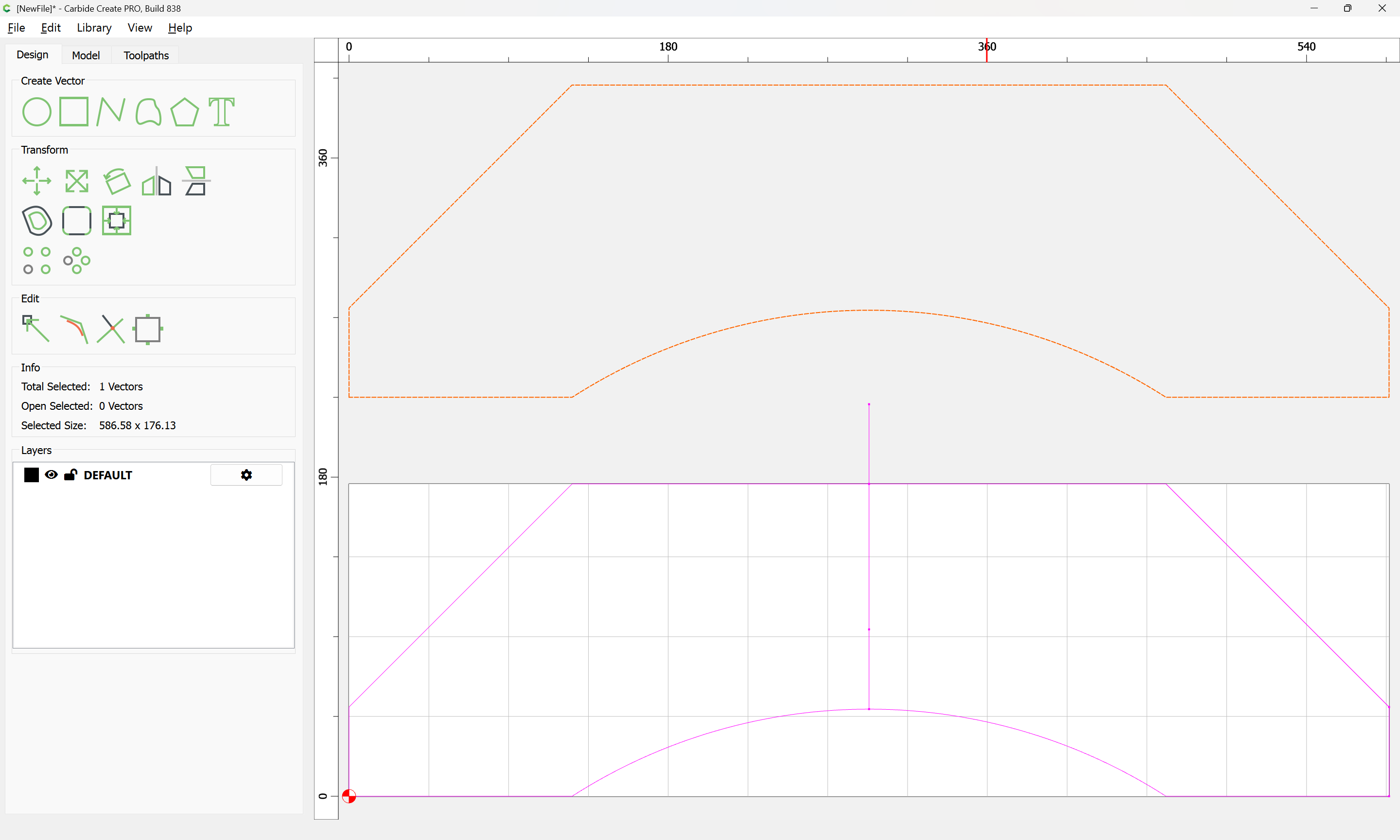
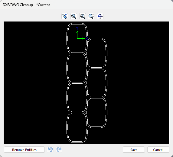
ArborPart1.dxf imports as described:
I am going to assume that what is needed is two levels (a screengrab showing the part in 3D, or an STL would help a lot).
Opening in LibreCAD doesn’t communicate anything to me:
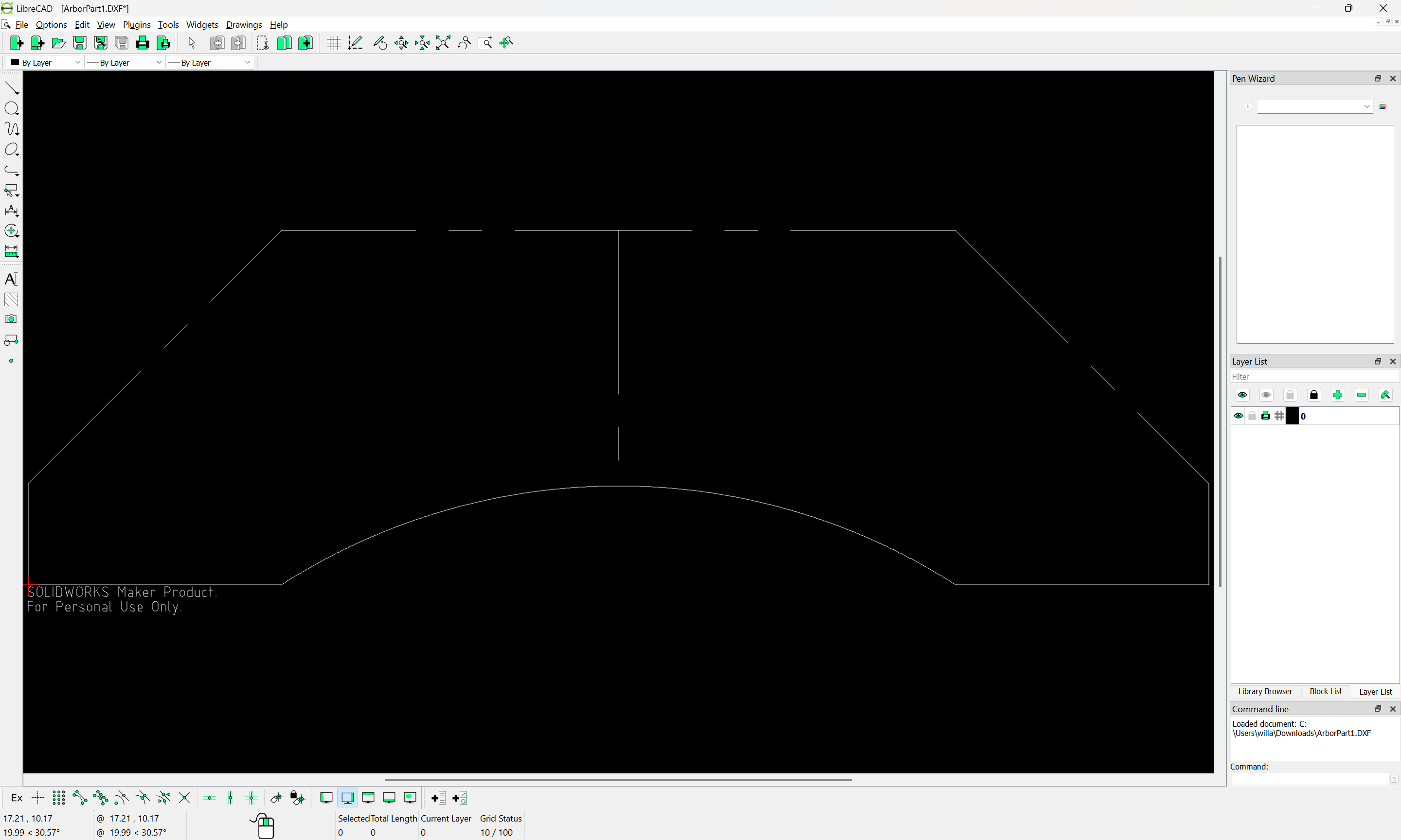
and exporting an SVG from it and then importing yields much the same:
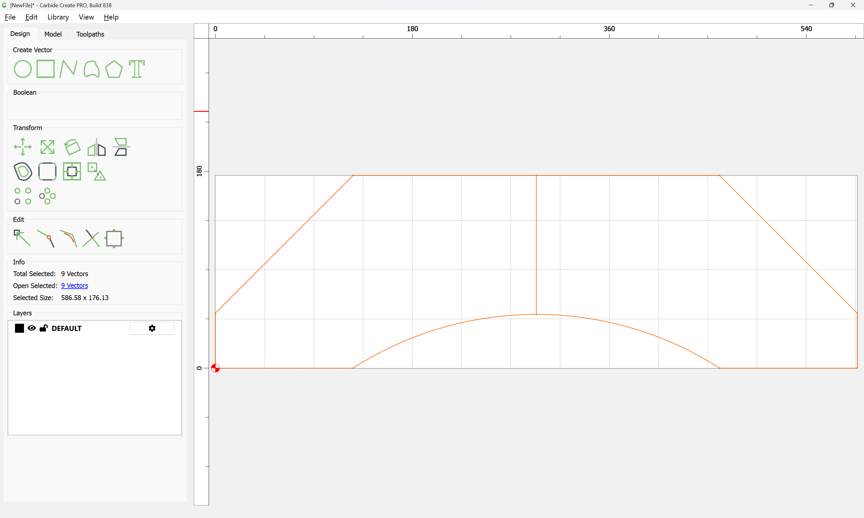
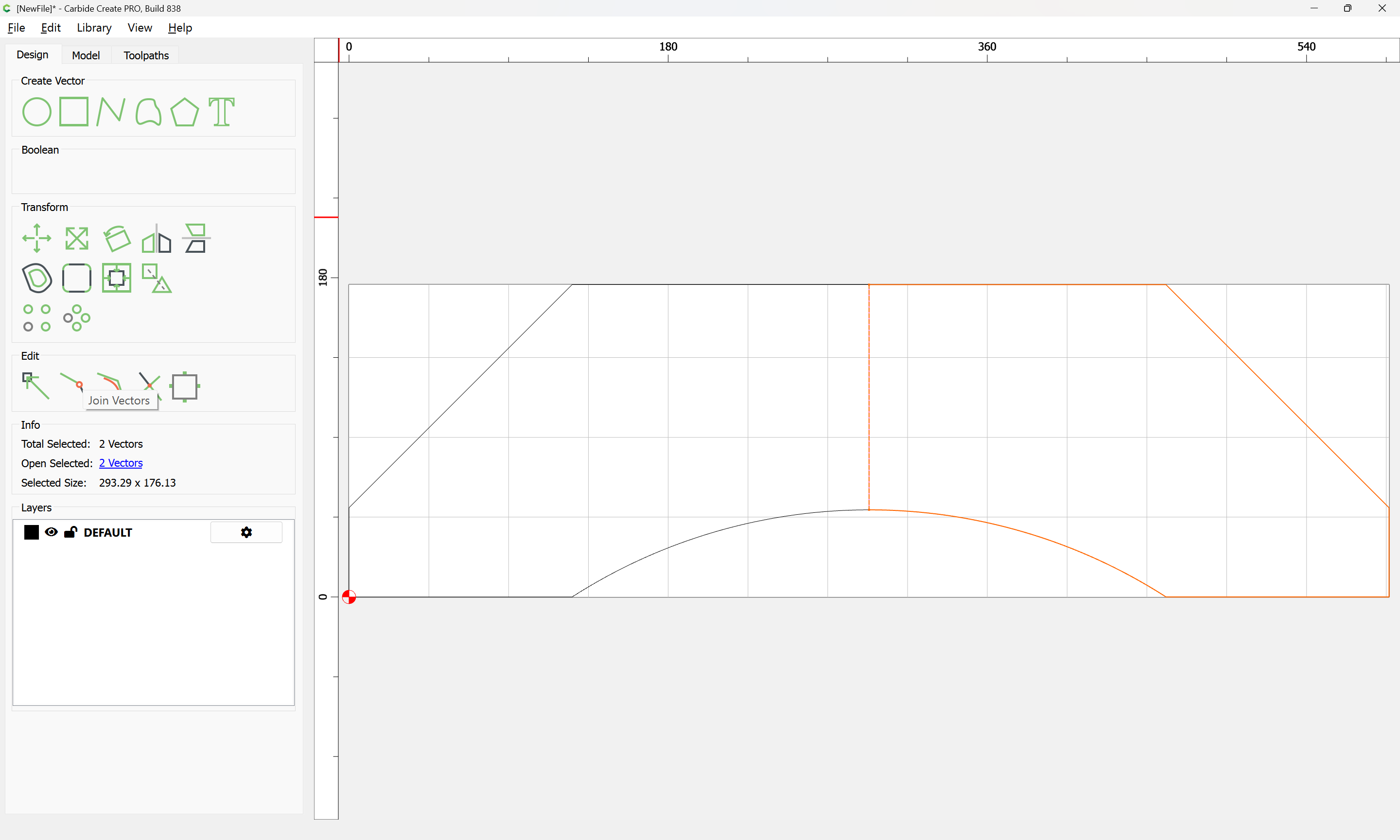
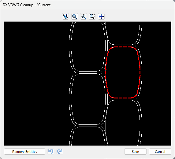
If we nudge things around with the arrow keys so that we can select only the perimeter geometry:

Then use Join Vectors:

Yes
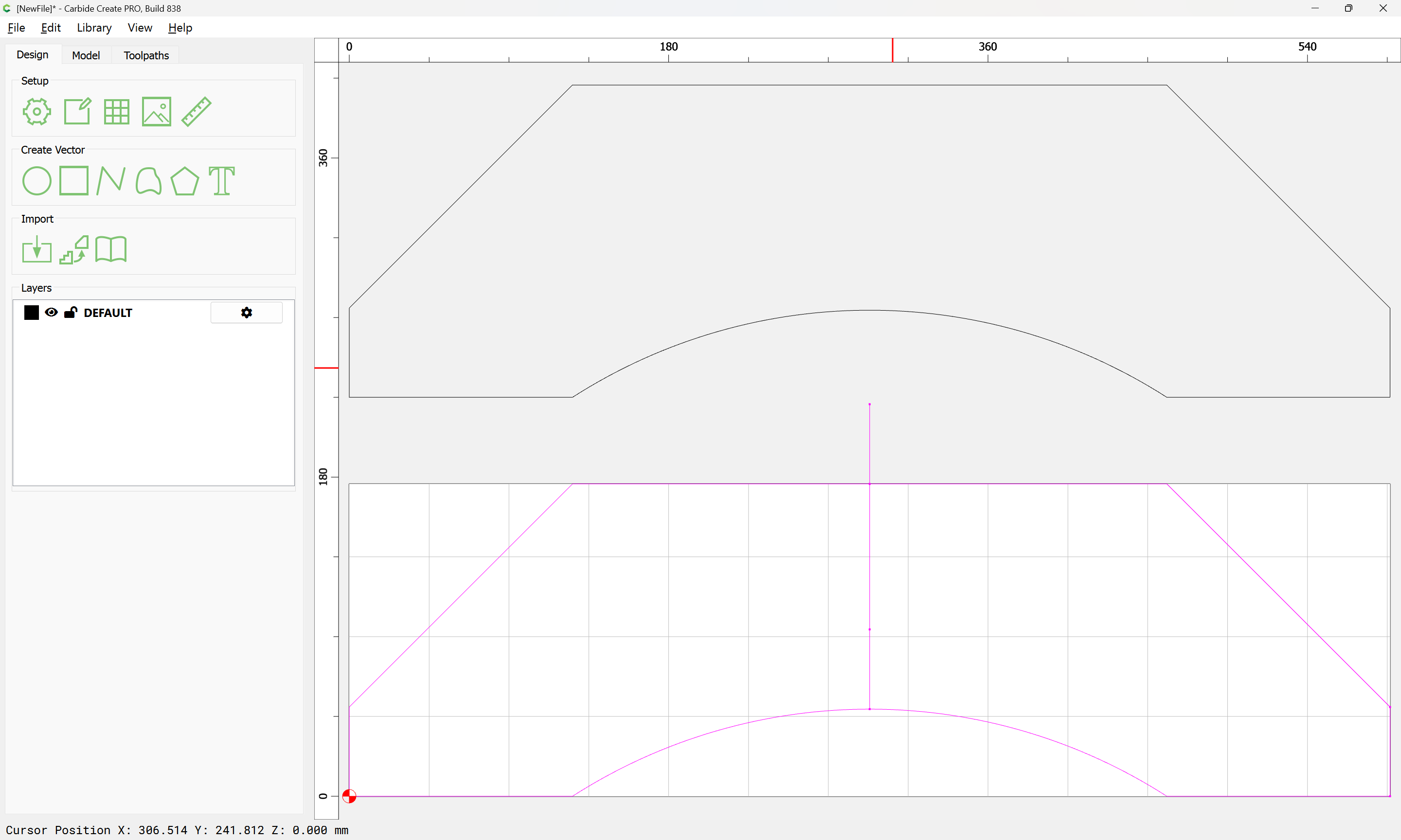
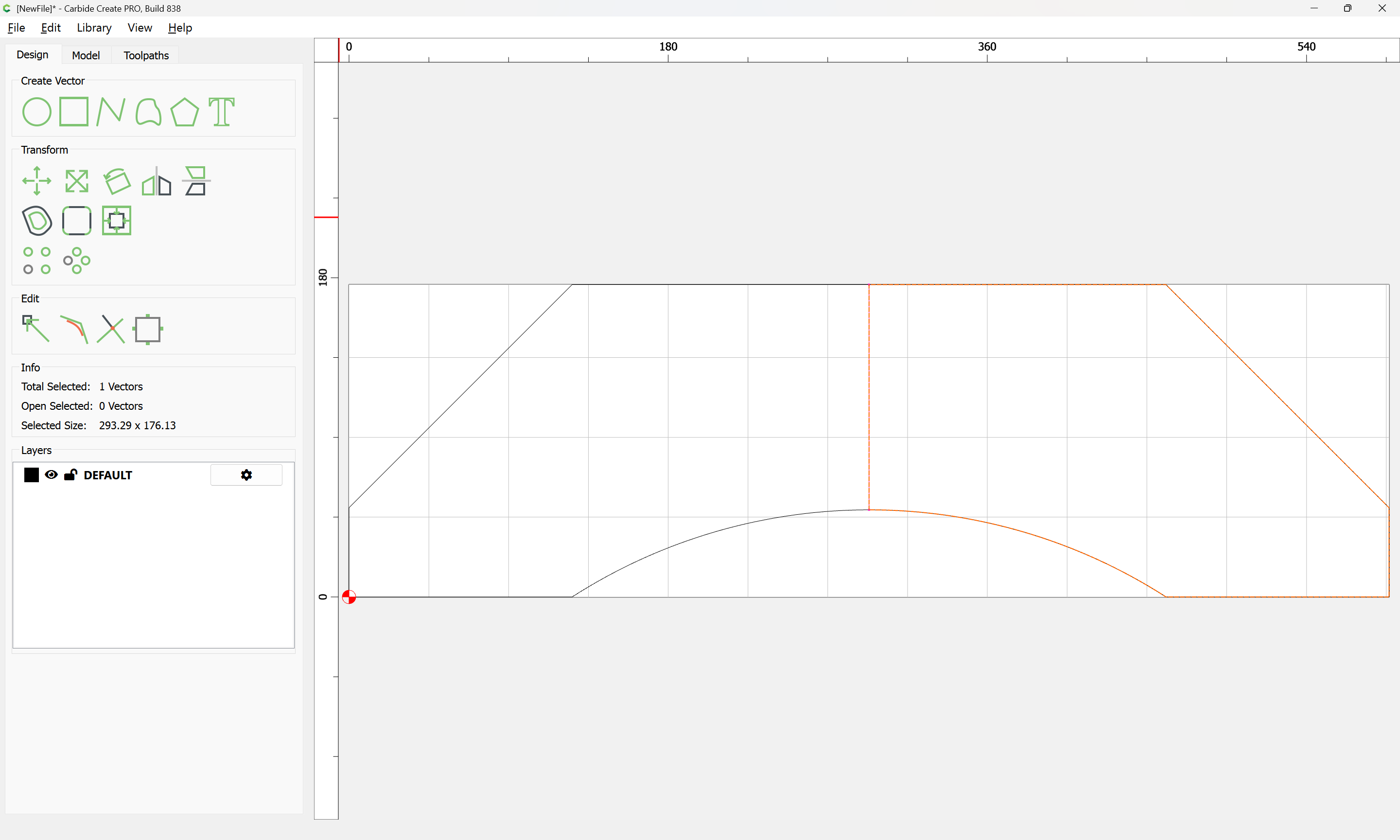
Cleaning up we arrive at:
If we actually need the division, then it is a simple matter to duplicate the closed geometry in place:
Use Snap to Node to draw in geometry which defines the division based on the open line:

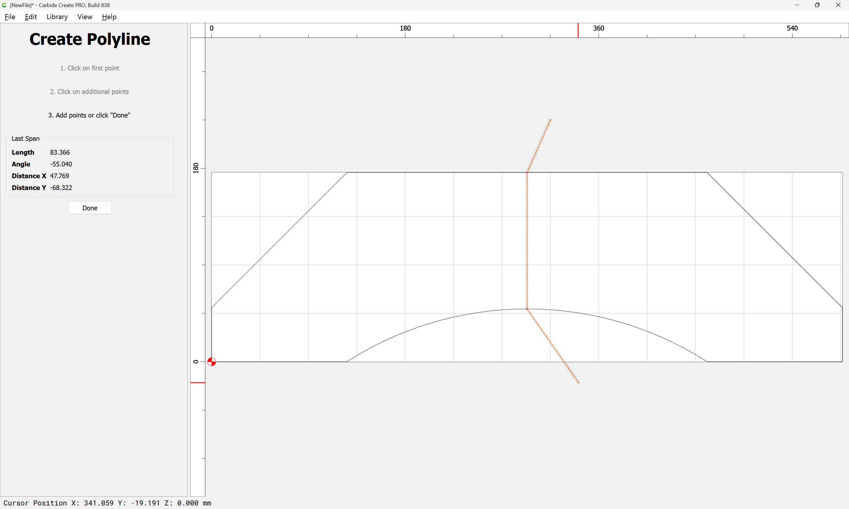
Done
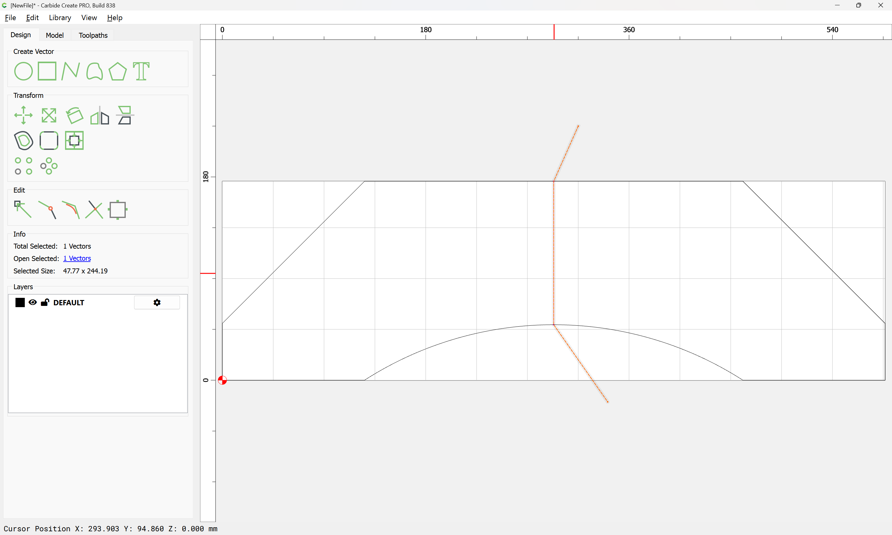
Select one of the duplicated perimeters:
shift-click on the drawn line to add it to the selection:
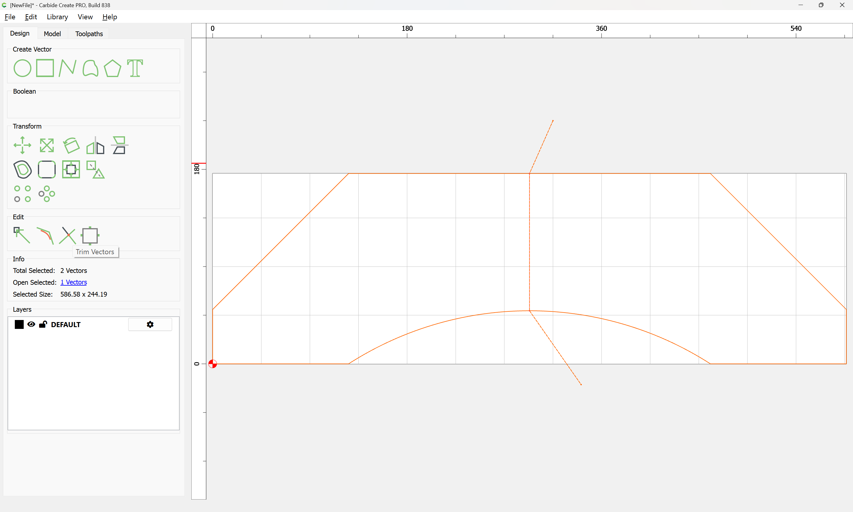
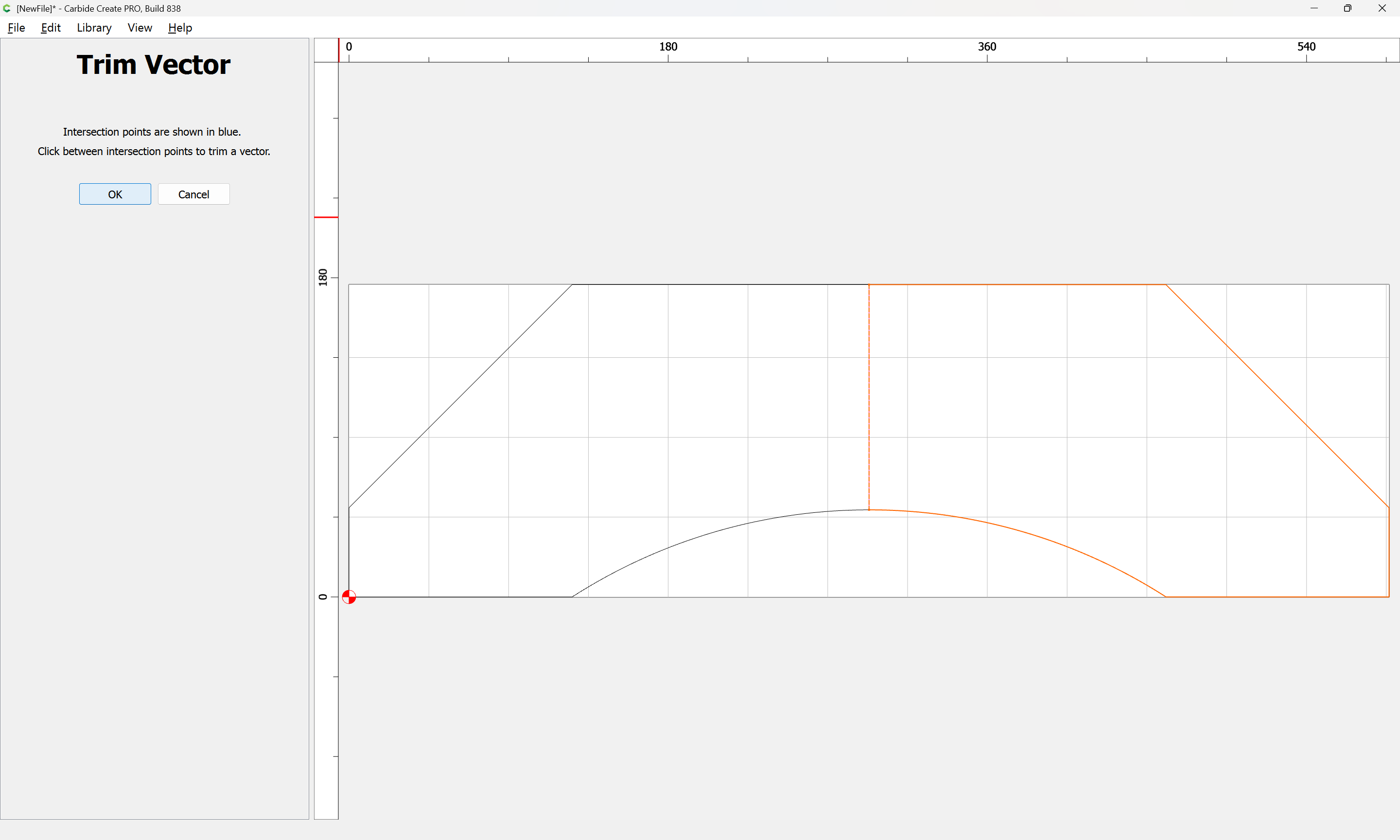
then use Trim Vectors:
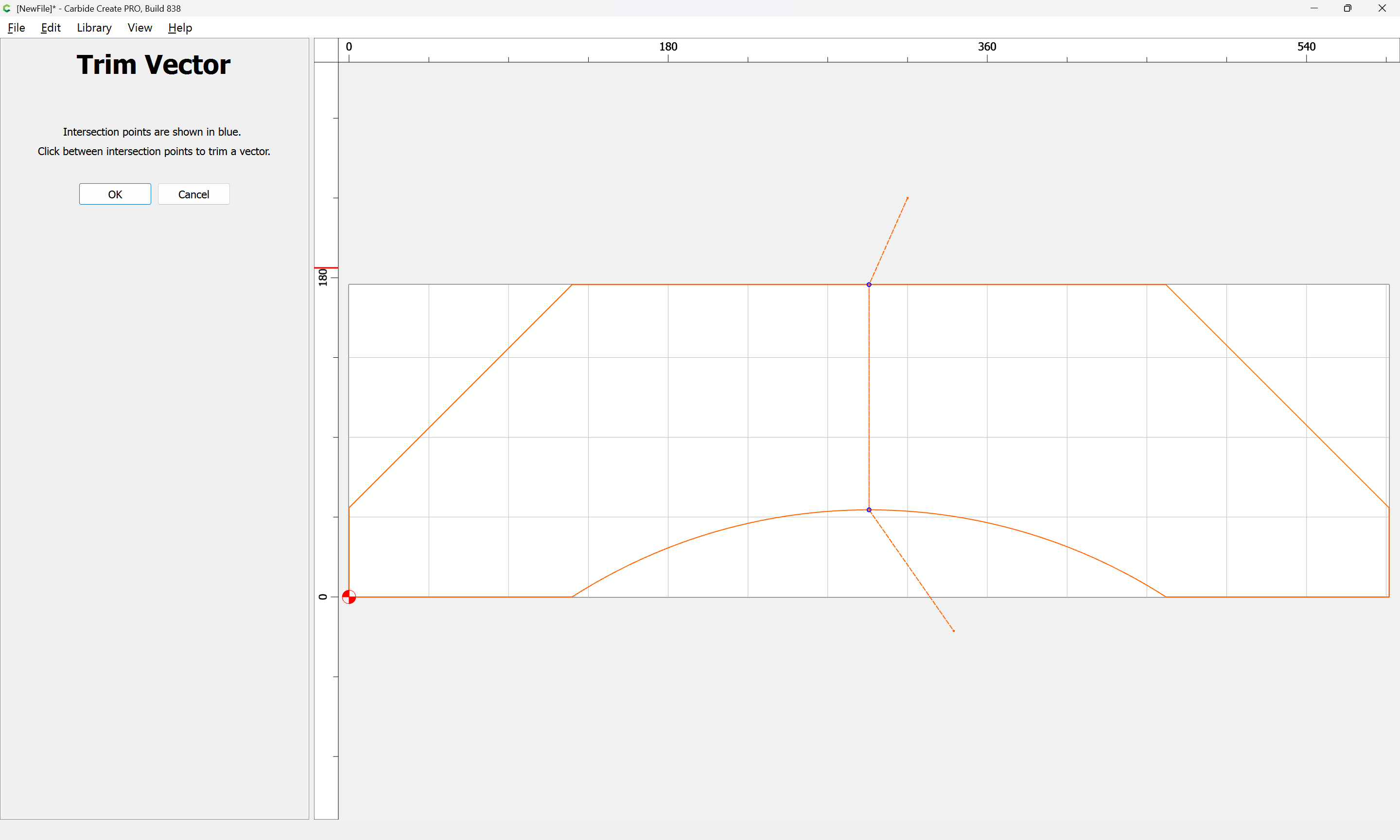
to remove what is not wanted (we will keep the right side)
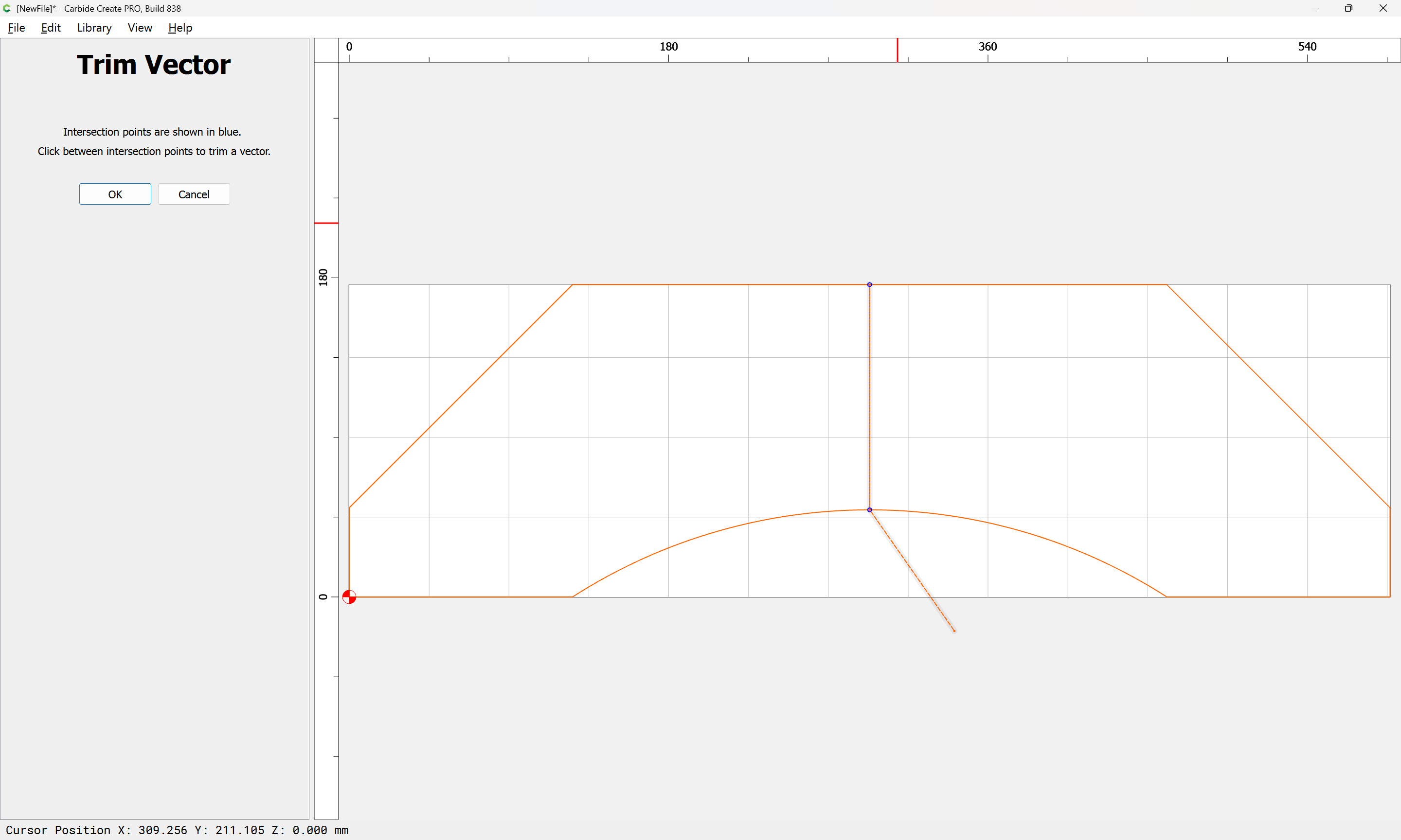
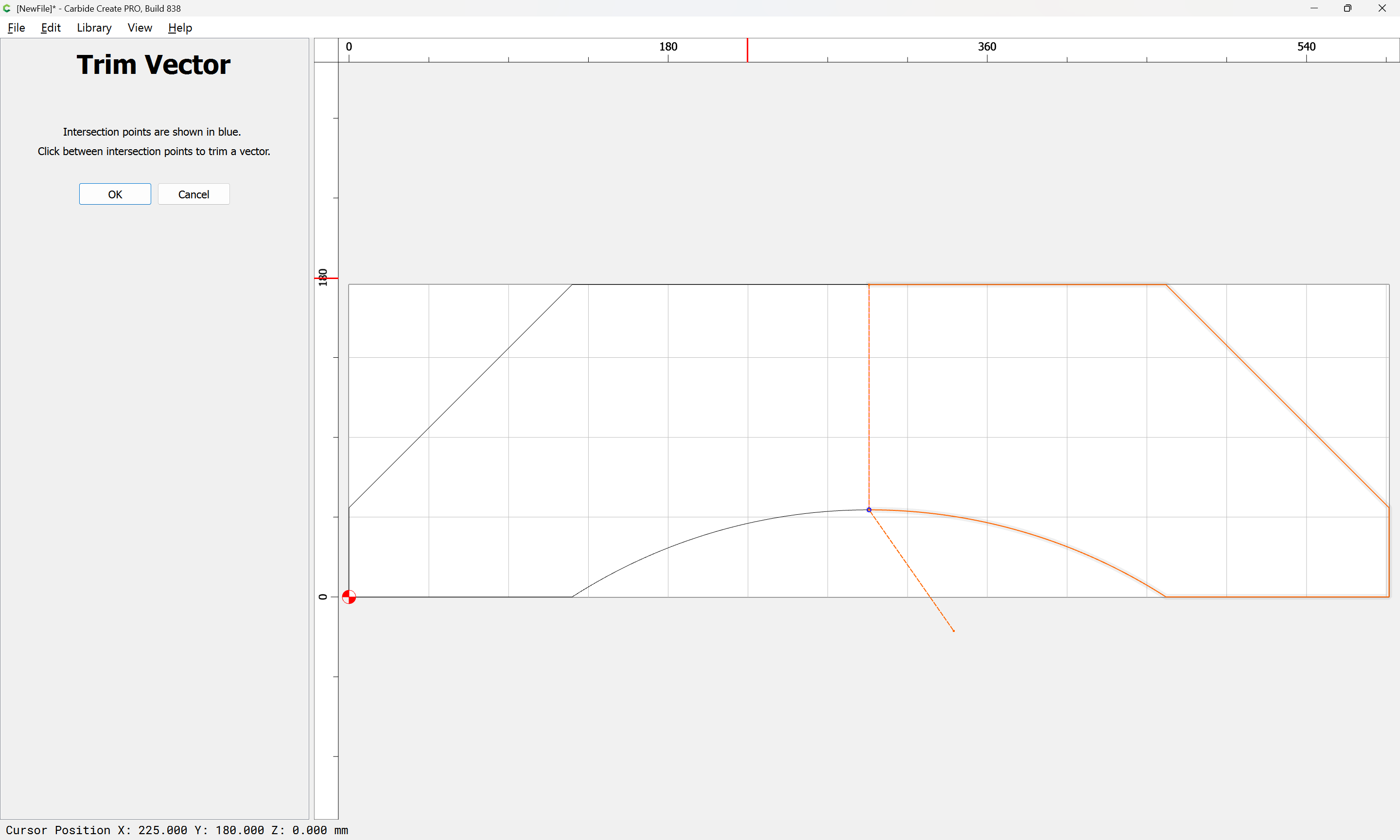
until we arrive at:
OK
OK
Use Join Vectors again:
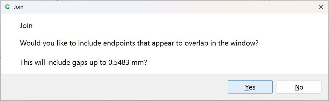
Yes
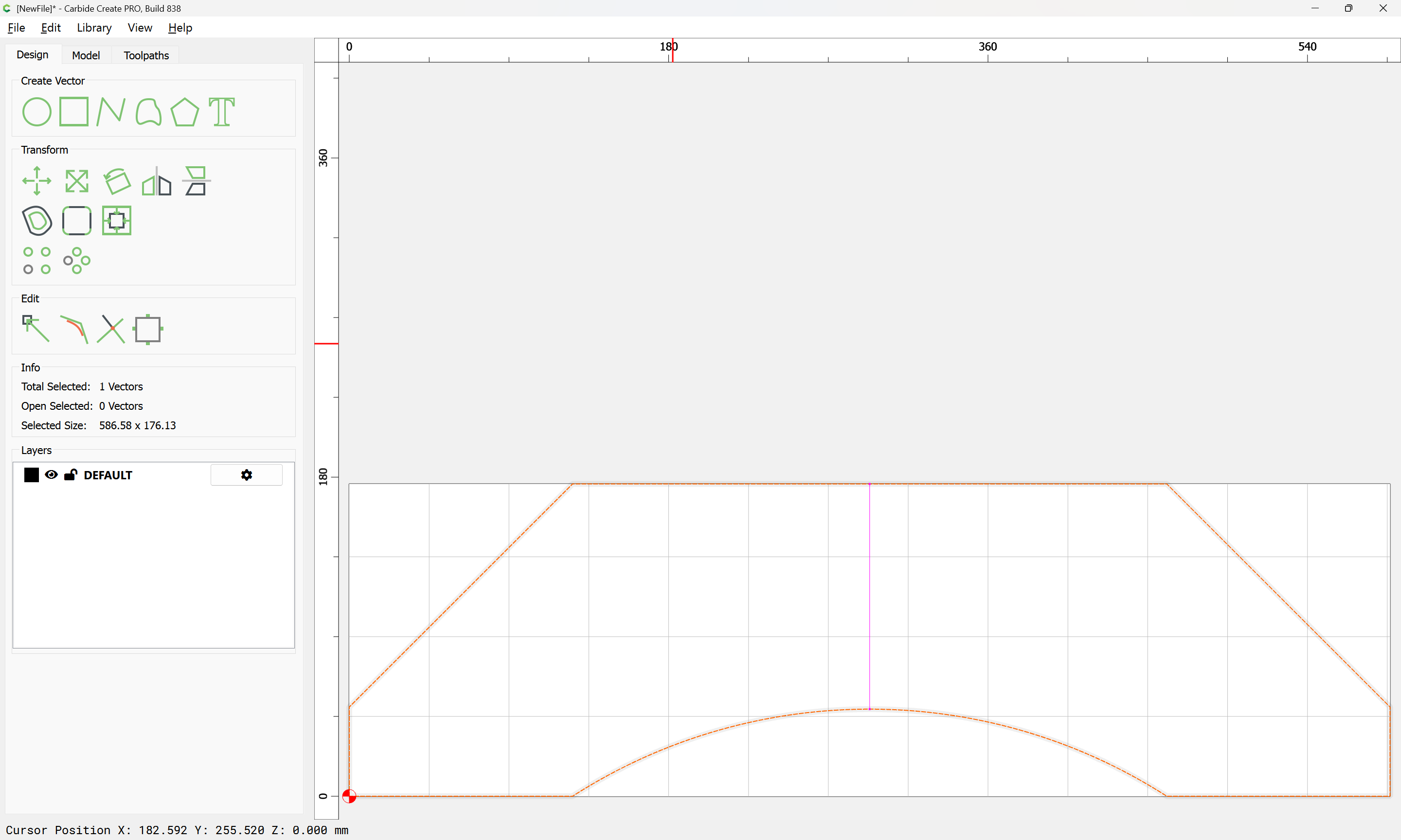
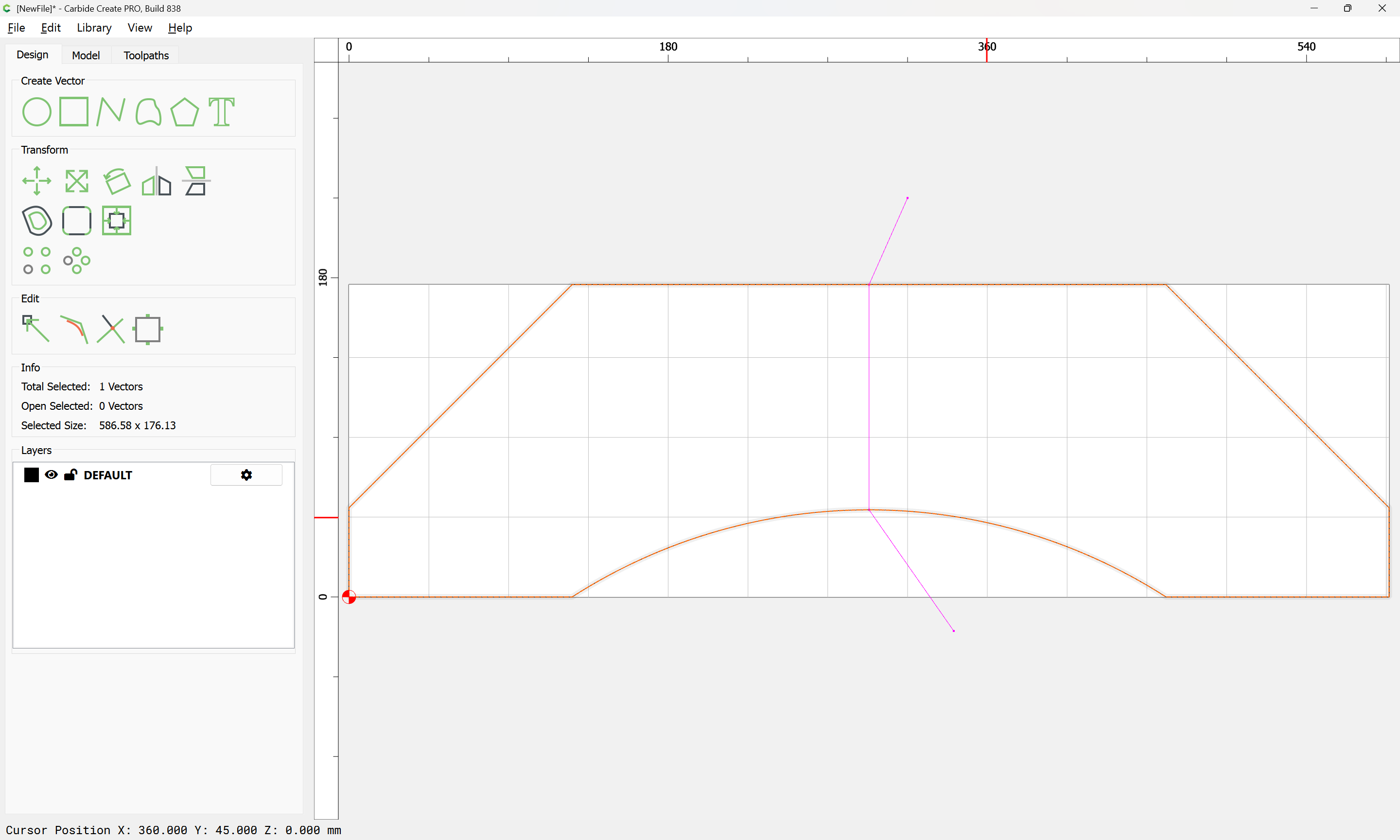
Select the original perimeter:
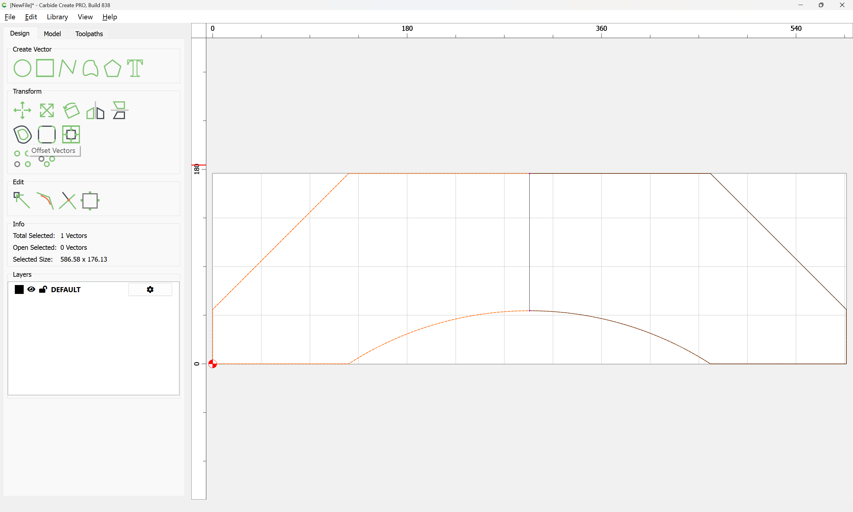
Offset to the outside by tool diameter plus 10%:
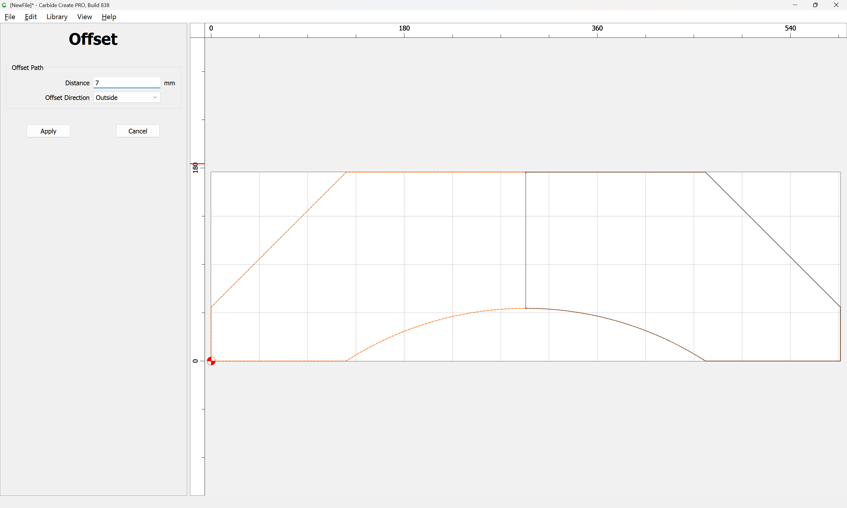
Apply
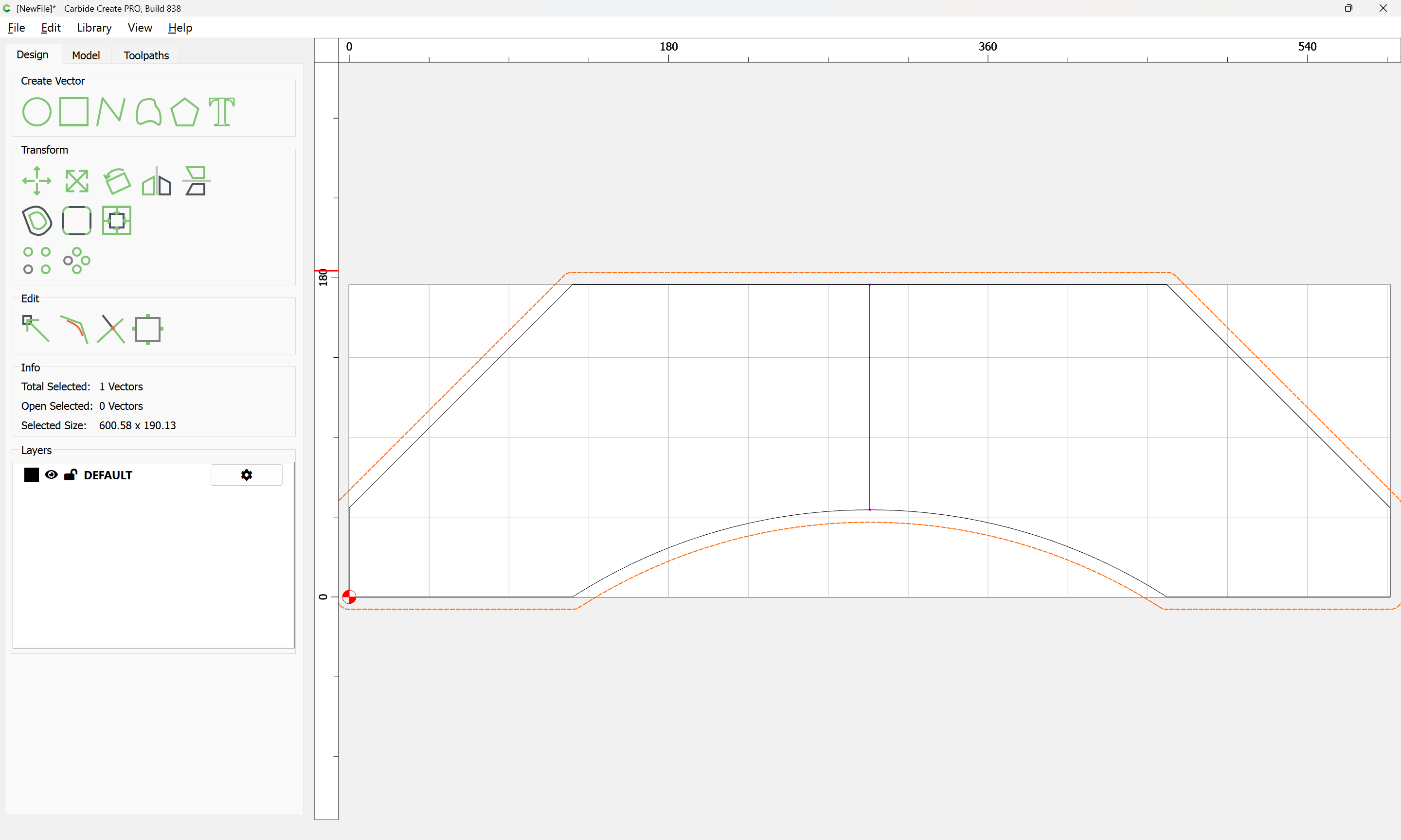
Add the trimmed section to the selection by shift-clicking on it:

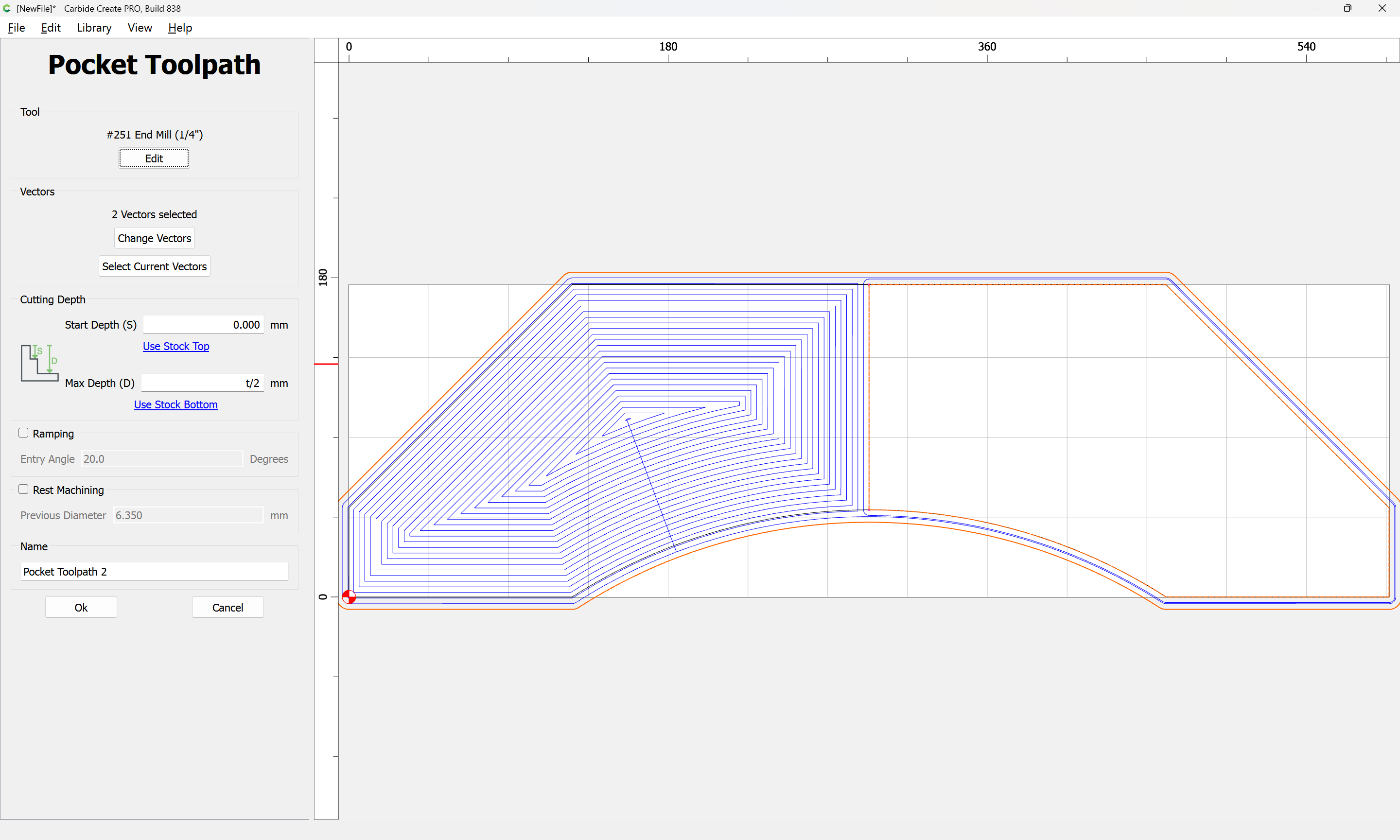
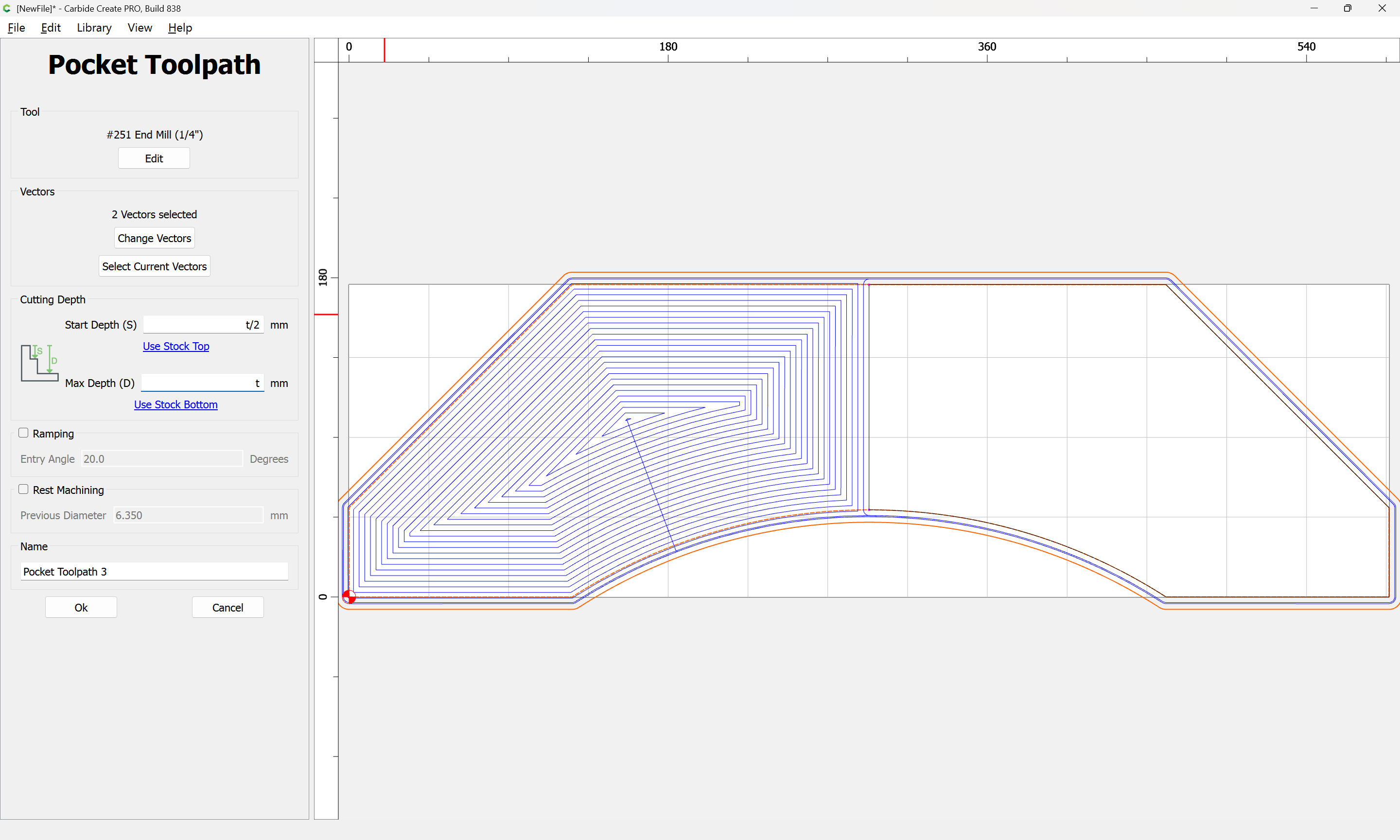
Then make a toolpath which cuts as deeply as is needed (we will assume halfway through the stock):
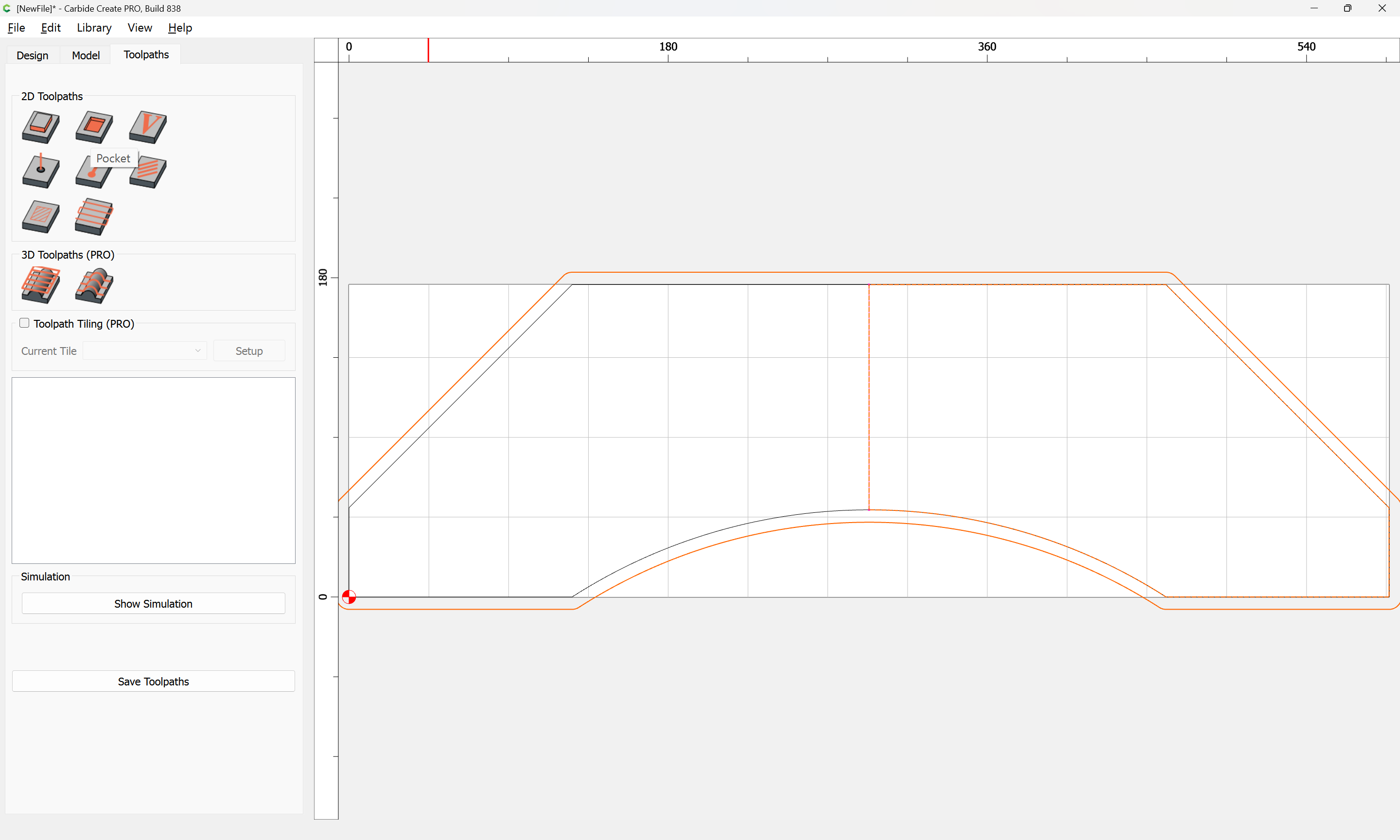
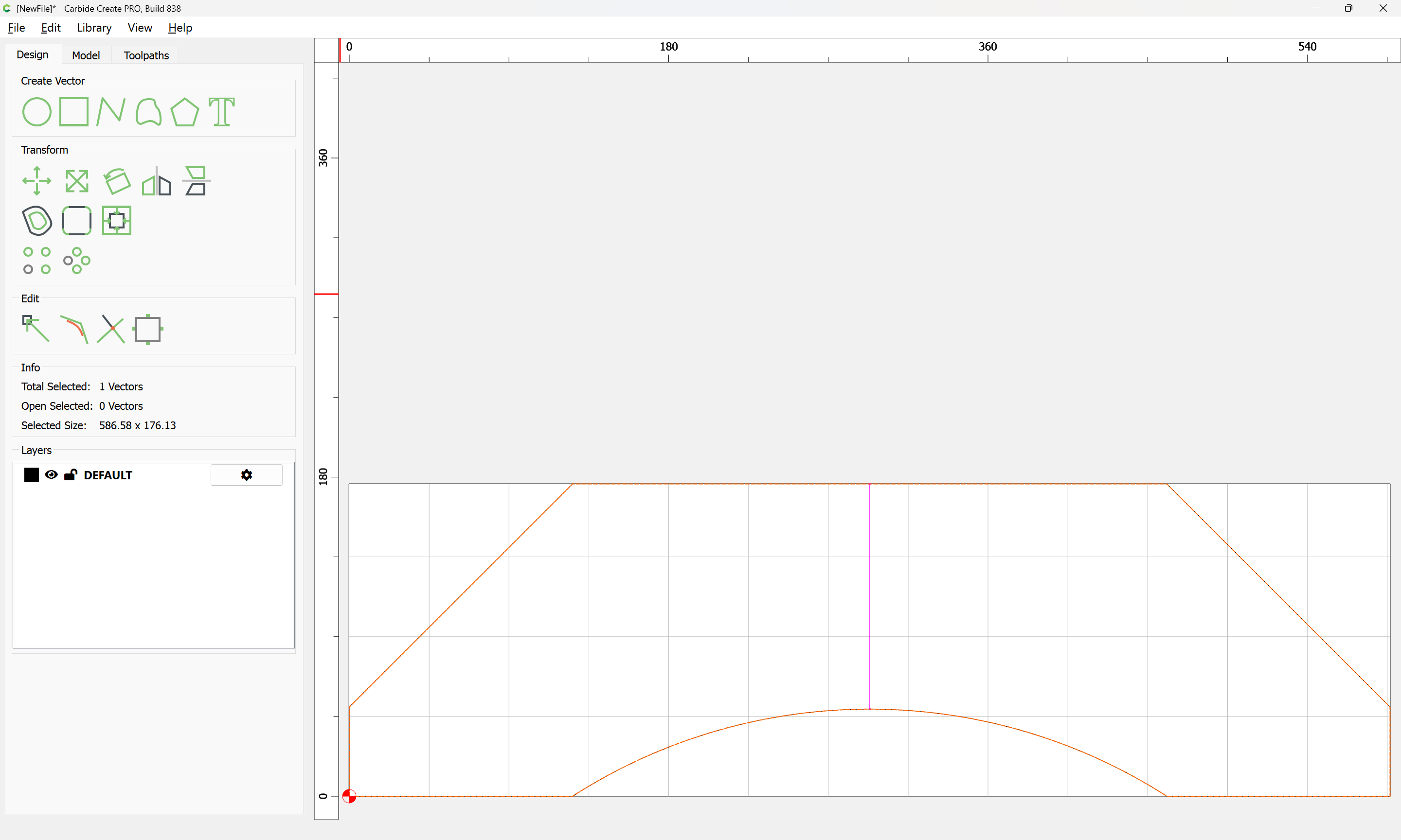
Then select the perimeter and the offset geometry:

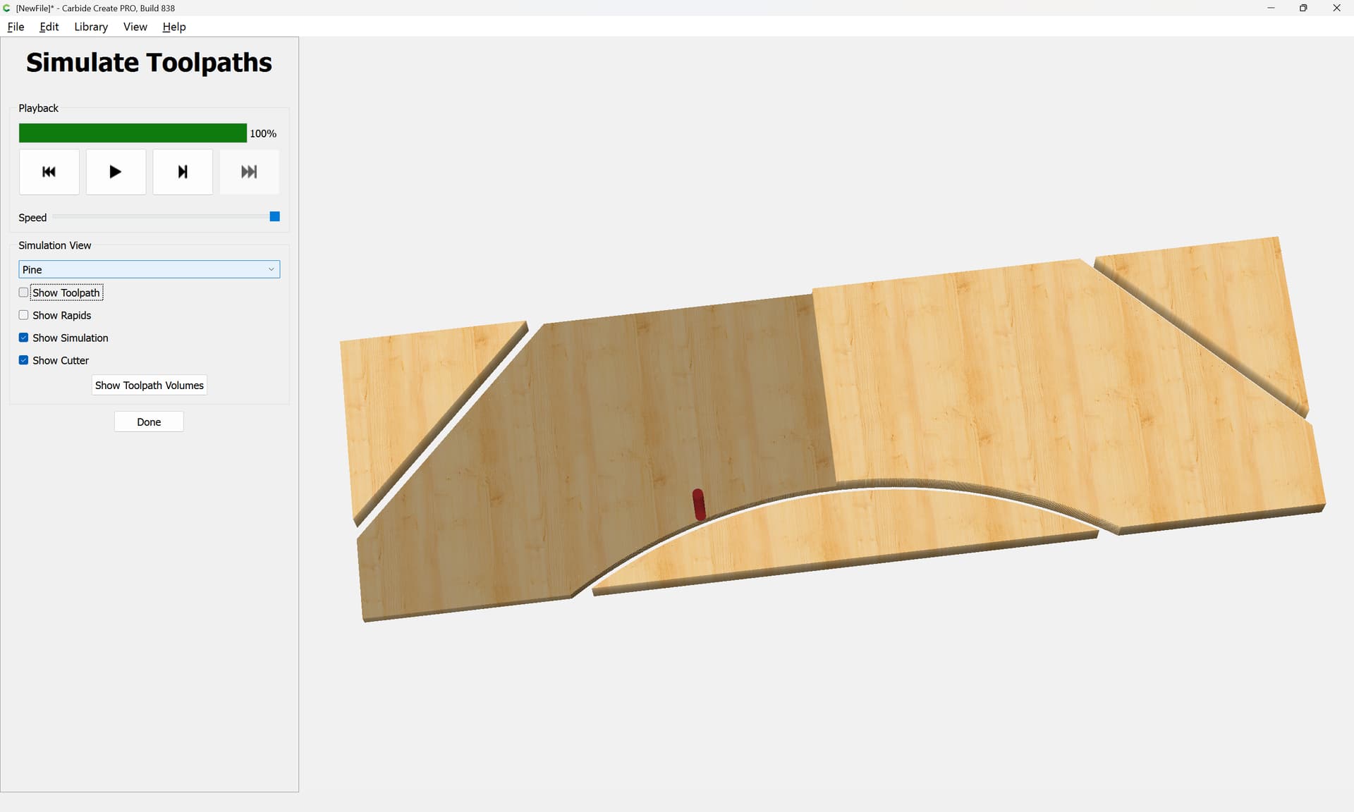
and finish the cut (assuming tabs are not needed):
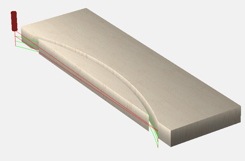
which simulates as:
attached as a v8 file.
ArborPart1_v8.c2d (260 KB)
1 Like
Presuming this is the toolpath you’re looking for…
You don’t need closed vectors to do a contour toolpath.
If you know the radius, draw it in CC & trim it a bit outside the shape for a lead-in.
If you don’t know the radius, use geometric construction (bisect an arc) to draw it.
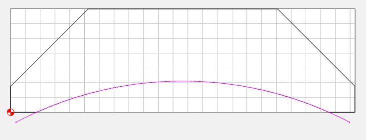
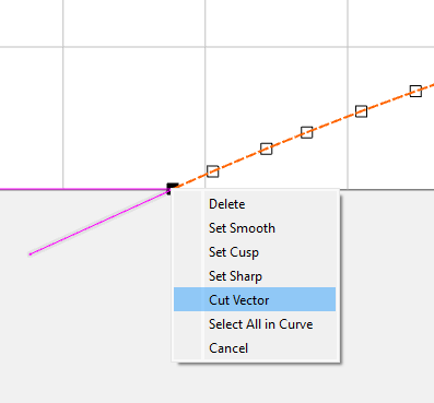
You can also just edit the existing vector, cut it at the arc ends, and add small lead-in/lead-out vectors.
2 Likes
FWIW, this would be quite simple to draw in Carbide Create if one had a dimensioned drawing:
or:
Note that MeshCAM is made by one of the partners at Carbide 3D and is bundled with the Nomad, moreover, there is a warning for this sort of difficulty:
1 Like
Or, for drawing this sort of thing:
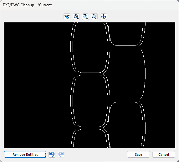
When you output a DXF from SW, there is a Remove Entities check box at the lower left
It can be a little laborious, but ctrl-select the lines you don’t want and then hit that button
Personally, I import SW DXF’s into my old VersaCAD 2D program for massaging…
1 Like
Thank you, thank you!!
I’ll be coming back to go through some of these techniques but by allowing it to join vectors then deleting nodes I got the path I needed. Then the tip about contours don’t need closed vectors did the rest.
Next step is to do a dry run, practice cut, then the real thing.
Oh, how I love a breakthrough after a serious mental block.
One concern about using Open Vectors — typically they only allow a slotting cut — where possible avoid slotting and add geometry and cut as a pocket
and/or
and consider leaving a roughing clearance and taking a finishing pass.
This topic was automatically closed 30 days after the last reply. New replies are no longer allowed.