Community challenge #25: Beyond the limits (closed)

Time for a new community challenge!

Make something that is larger than the work area of your machine!

I’ll use one of @MarkDGaal’s pics of a tiling setup as an illustration (hope you don’t mind Mark, I just like that picture)

image

But you could also make something that is assembled from parts that each individually fit in the machine work area (I’m looking at you, Nomad owners!)

Rules for this 25th challenge:

  • submit your entry in this thread (you can post multiple entries if you want)
  • you must use a Shapeoko or Nomad
  • At least one dimension of the final piece must be larger than the largest dimension of your machine’s work area.
  • post pictures of the project (we like seeing WIP pics in addition to the glamour shots)
  • posting your project to CutRocket will get you a +2 bonus on the vote tally.

Timeline:

  • Deadline is set to Oct 17th 2021, midnight PST

  • there will then be 7 days for voting.

    • voting will be open to legit community members only, and the jury reserves the right to remove votes from “outsiders”, and will also break any tie.
  • First place: a Get A Grip workholding set + a McEtcher diamond drag bit

  • Second place: a Get A Grip workholding set + a McEtcher diamond drag bit

  • Jury’s prize: a Get A Grip workholding set

Along with mucho cool swag

image

Let’s hone our tiling/joinery skills together!

6 Likes

Two potential strategies here would be joinery, or tiling.

For joinery, there are many techniques:

Rabbets:

Dovetails:

Knapp joints:

Box (sometimes referred to as finger) joints:

and there are of course, regional variations:

Japanese:

Note that some joinery techniques will require a fixture at the front of the machine to hold boards vertically such as:

For tiling, one technique is to machine pairs of holes which will match up w/ dowels which are placed on the machine:

For making the files for this, see:

and see:

and

as well as:

Anyone who has difficulty should feel free to check in at support@carbide3d.com and we will do our best to assist.

4 Likes

This article also had some good tiling info for the shapeoko. CNC the Maker Workstation | Popular Woodworking Magazine

2 Likes

I’m going to submit the Y-axis of the mill I’m building. Not only is it larger than my Nomad’s work area, I think my Nomad can fit within its work area:

To build it, I used the Nomad to machine:

  • A few spacer plates that provide a dead-flat surface between the rails and the extrusion (hard to see them in the picture above but if you zoom in they’re there.
  • A plate to attach the servo motor to the extrusion:
    • This was a 15mm-thick (0.6in) plate so it was a little bit of a pain to work with. In the end I:
      • Used a 6mm endmill for the outer contour and large ring - the 6mm endmill had a cutting length of 15mm.
      • Used a spot drill to spot the holes, then drilled them with a small benchtop drill press.
  • A pair of supports to attach the ballscrew support to the extrusion:
    • Unlike last time, these parts were 24mm in height. For the holes I again used the spot drill + drill press method but I also needed to machine the circular cutouts for the ballscrew support and I don’t have any endmills that can cut 24mm deep. To get around that, I:
      • Used one setup to cut out the two parts on their side:
      • Used a 6mm endmill with a 21mm cutting length for the upper, wider circular cutout. This was enough to reach down to the little notch.
      • Stuck that same 6mm endmill just a few mm out of the collet holder so that it would have enough reach to get to the bottom slot. Thanks to the slot above, there were no issues with rubbing.
      • Unrelated to the above but since I can’t un-indent, this was also the first time I successfully used a dual-station setup to cut. I was able to machine both work pieces in one setup:
  • 4x plates to attach the machine bed to the Y-axis rails:
  • A plate to attach the machine bed to the Y-axis ballscrew (the only thing that was straightforward)

Here’s a picture of the servo assembly:

And here’s the whole thing from the bottom:

And a short video of the thing moving

And who knows, by the time the contest ends maybe I’ll have done the X-axis too!

I’ll add that the servo assembly and bed designs I went for weren’t my first choice, surprise surprise because of the Nomad’s work area.

For the bed, I wanted to make one big mounting plate that would fasten all of the blocks to the bed in one piece. Unfortunately that wouldn’t easily fit in the Nomad’s working area, so I went for this option instead: using the bed itself to glue together the various blocks. This is an SMW threaded table and the holes go all the way through so I just bolted into the bed from underneath using the existing threaded holes.

For the servo assembly, I at first wanted to make something like the commercial options: image
but doing that would require a lot more reach than the Nomad has easy access to, as well as larger chunks of stock than I have on hand. I’m not sure even my modified Nomad has enough height available to more the back and front holes for the servo/support.

Instead, I broke the motor support into two parts with different responsibilities:

  • A plate to mount the servo. This plate only has to deal with torque: when the servo motor rotates the screw, this plate just has to provide the equal and opposite reaction. It doesn’t need to deal with any axial forces at all.
  • A pair of pillars to mount the ballscrew support. These pillars don’t have to deal with any torque (there’s a ball bearing inside it after all), they only have to handle the axial forces from the ballscrew.

Thanks to that the servo assembly ended up looking a bit weird but I’m hoping it’ll do what it needs to do.

16 Likes

Making larger RC Planes from smaller parts. (What else would I post about!)

My favorite method for creating RC parts that are larger than my wood stock and/or machine is by “Dovetail Shaped Splitting Lines.” At least that is what my CAD program calls them. I am using devCad-Pro. (https://www.devcad.com/eng/default.asp) devCad has a command that will allow you to split a large part into multiple pieces and use straight or dovetailed cuts. Here’s a picture of what I am talking about. Notice that the dovetails are rounded so they can be cut by a router without causing gaps.

The only way I can think to do something similar in Carbide Create is to create a “cutting” part that is basically a square with one side being the dovetails. Then move this cutting part until it’s over the part to cut completely covering one half. Then copy that entire assembly and move it somewhere. Use the Boolean Intersection and subtraction functions to create two halves. One thing to watch for is making sure your cutter can follow along with the outside trace flush against both parts. Making a circle the size of the cutter and moving it around the split lines is one way to check.


Cutter.c2d (40.5 KB)

The RC plane builders have been struggling with the size issue for a long time. This is due to a number of factors, but mainly to the size of available lightweight balsa wood boards. While bigger pieces exist, they are very expensive. Typical wood sizes that are easily available are 4 x 24, 3 x 36, 4 x 36 and 4 x 48 inches. So to build bigger planes, creative ways to splice pieces together have been occurring for many years.

Here’s an example where I used a bunch of dovetail joints from a build this year. It’s an older/classic plane from 1979 that I redesigned for electric power. I basically designed it to be lighter and able to use my Shapeoko to cut the parts. The fuselage sides are just over 70 inches long and over 6 inches wide. Much longer than my Shapeoko and longer and wider than my wood.

The above is 3/32 Balsa and 1/16 ply. I glued them together with normal aliphatic wood glue (Titebond). Since the glue is stronger than the wood in this case, you end up increasing the strength of the piece. Laminating the balsa and ply together makes it even stronger. In this case, I used 3/32 balsa 4x30 inch sheets and 1/16 ply 12x24 inch sheets. These were cut with a tiny 1/32 inch bit.

The total build consisted of 14 sheets of 4x30 3/32 balsa, 4 sheets of 4x30 ¼ balsa, 4 sheets of 12x24 1/16 ply, 1 sheet of 12x24 1/8 ply, and 1 sheet of 12x24 ¼ ply.

Design photos:


Here are the final parts separated by the wood type needed. I then used devCad Pro-CAM to lay out the parts to fit the wood and create the tool paths. Dovetail joints were used for the fuselage sides, fuselage battery deck, wing main spar, and wing trailing spar.


Mama_MiaParts.dxf (1.9 MB)

Here’s the CAM Toolpath output screen in devCAD. There are 14 pages of parts laid out for 4x30 x 3/32 sheets. This is the output of the CAM Profiling wizard. You just select the parts to be cut, tell it the wood size and where you want your zero point to be (and some other properties) and it will assign parts to your wood and create the tool paths for you. It works really well and is one of the driving reasons I use devCAD.

Glue everything together and you get this:

Add covering and the rest and you get this.

A 65-inch wingspan and 75-inch length MamaMia from 1979!

Wing and stabilizer were designed in WingHelper (https://www.winghelper.com/default/) Fuselage in dev Fus and basic design and CAM work in devCad-Pro CAM. (https://www.devcad.com/eng/default.asp) I have created a custom Post Processor for devCAD so I can use tool changes. (One tool for cutting parts out and one for engraving part names on the pieces) They provide a generic GRBL post processor that works fine on the Shapeoko but it does not support tool changes.

30 Likes

Wow.

Competition is on :sweat_smile:

Awesome. I hope you’ll consider posting more about this project

I have and will, the main thread is here :slight_smile:

i was going to put in a plan but the plane is crazy cool and i was already hoping for second or third :slight_smile:

Don’t forget there is always jury’s prize, which may or may not follow the vote ranking :wink:

4 Likes

Here’s one of the first things I made on my Shapeoko.

A really good friend of mine is a somewhat accomplished musician with a bit of a habit of buying vintage analog synths and rack mount gear. His gear had badly outgrown the old Ikea desk it was concealing and something bigger was necessary. We looked at lots of ‘studio desks’ online (during Covid lockdown) and saw that the only ones which looked nicely made and well designed cost more than a used car, so it was time to get the tools out.

We did a very simple profile outline of the desk top based on how he wanted to sit at the desk with easy reach to the rack and shelf pedestals (that turned into two rack pedestals half way through) and then modelled up some options for the desk in CAD.

I printed the parts on my Prusa so we could check out what it was like in 3D and the customer could see whether the proportions worked etc.

To make sure the desk was rigid and didn’t sag or vibrate I put a torsion box across the back. This is dual purpose, it’s both a cable management area and the torsion box as there are many many cables. Here’s the CAD render of the inside of the torsion box with legs attached.

This was, fairly obviously, designed to be cut on my new CNC toy.

First cuts were the short internal braces, these were easy enough I left tabs (as I had not yet discovered blue tape and CA glue), sanded them smooth and then used chisels to square out the corners on the tenons.


Unable to put off the large tiling job any longer I bored a bunch of holes in the spoilboard to accept 10mm aluminimum pegs.

These were just cut from 10mm Aluminium rod and were, fortunately, soft enough that when I sent a toolpath through them the damage was done to the pegs and not the cutter. These pegs gave me a Y axis reference to line the board up on to slide it along for the tiling.

For alignment in Y I marked a cross on the workpiece and then used the phone camera as a magnifier to line up a V bit on the mark. You can repeatably get within 0.1mm like this when you can’t use any better method.

I set this mark up as the workpiece zero in Fusion for both setups and then got to cutting. The real alignment test was the chamfers meeting on the long edges, it was within 0.1mm and sanded to invisible pretty quickly.

Then the back board of the torsion box, same process

I also CNC-ed out the mortices in the top and bottom boards to make sure they were actually in the right places, same trick marking zero and sliding along the Y axis pegs for alignment.

The mortices were a PITA to square out with chisels in this plywood, I assumed if I just made them tight it would be ‘easy’ to open them out, I was wrong. I also didn’t bother stepping down from 1/4" to 1/8" to get squarer corners, that was also a poor decision.
After fighting with the mortices and tenons I now had a torsion box I could assemble with pretty tight joinery, I’d left a couple of mm of stick through on the tenons so that I could sand them flush after assembly.

Glued together, here’s the inside of the cable box. The front panel is a double layer laminate, not for strength but just to look like a big structural girder. I made the inner layer on the CNC and made a(nother) mistake, I cut it to target dimensions and thought I could laminate the two together with decent alignment. I should have left a couple of mm of extra around all the cutouts on the second piece and used a bearing guided trim router bit to match them up, there was was too much sanding for one lifetime, all by hand as I couldn’t get any power sanding tools inside the cutouts.

With RGB LED strips, of course

Next up it needed legs, obviously these were from the CAD and to be cut on the Shapeoko, front side first, cut and V bit engraved.

The legs were spaced 36mm at the top and 18mm at the bottom so the back where they bolt to the torsion box front plate had to be angled, another job for the Shapeoko (that’s a test piece, which is why it has twice as many holes as it should have)

A major reason for the legs being skins of ply instead of solid wood was to hide a lensed LED at the top of each light to project down onto the floor at the foot of the leg.
They’re all attached using M8 stainless hex head with domed nyloc nuts, meaning all the bolts are custom trimmed to length…

Here’s the torsion box on the underside of the desk top, I had to use the track saw and hand router on the desk top as it was somewhat larger than my SO3 XXL…

The pedestals were angled backward to make the equipment easier to use, we cut these on the table saw, again probably a mistake, I think I should have just cut them out on the Shapeoko to get more accurate dimensions than my mark up on the ply. The Shapeoko was used to do the V bit engraving on the sides, stepping down 0.1mm at a time until the engraving looked right.

They started off with some simple ovals in the back as cable management apertures in the bracing bar, however when I started to add some notches to help with cable management these started to look like something else to me, good thing the Shapeoko doesn’t care how complicated a shape you ask for…

The other cab was similar, but intended for shelves to start with before it became rack as well, so the rear cable management ended up a little different.


And finally, after lockdown, we finally got to put it in the van and take it to it’s new home

I hope that’s an enjoyable read, I learned a lot of things making it.

31 Likes

Looks like @Moded1952, @SLabuta and @LiamN may have scared away other contestants with their over-the-top entries :sunglasses:

@LiamN, just being curious, given how much plywood (or any wood really) costs these days, did you estimate the total cost of that project ? I’m sure it’s still much less than what your friend would have paid for a commercial option, but it can’t have been cheap either :slight_smile:
The torsion box part reminds me of @wmoy’s Skeloko!

3 Likes

I was more hoping to entice others to post what they were doing :cowboy_hat_face:

Fortunately we bought the 24mm and 18mm BBP ply at the start of lockdown before prices went silly, I think the ply and the American Walnut we used for the hardwood trim was about £450 from SL Hardwoods, it’s almost twice that now. There was then all the extras, LEDs, rack rails to bolt in, assorted M8 and M6 stainless fasteners (mostly from boltbase, great supplier) and some Osmo to finish it off, over £500 certainly but that’s < 1/5 of what you’d pay for a desk that has real joinery rather than Ikea style assembly bolts so far as we could tell, plus it was designed entirely to how this individual wanted to work with it. It seems musicians are quite picky about instruments, racks and patch cabinets on the desk, in the desk, under the desk etc. I just don’t understand that sort of obsession with tools… :face_with_thermometer:

Yep, it was very much echoing the braced girder industrial look.

4 Likes

My youngest wants to be a wizard for Halloween this year, and I assume you havn’t been wizard costume shopping lately but the options are either Harry Potter themed or Gandalf. He wanted to be a wizard in a blue robe with a cool staff.

So I had him draw roughly what he wanted on paper, I put that in inkscape and then we sat down to learn how to use Carbide Create and got to work (It doesn’t look like I can publish the cutrocket project since I didn’t do anything in fusion)


I didn’t have a working bit setter so I made sure to leave a Z reference I could use to re-zero after bit changes (the bitsetter works now and I used it later in the project)
But for my first 3D & first double sided project it went really well.


The routed channel in the inside is for a short LED strip light.

Ok now for the squirrely part.
We had found a gnarly stick on one of our daily walks. He said it would make a great staff. but I needed the end to be a slightly smaller stick.

So I clamped it into the shapeoko


I intended for it to be a two sided machining operation, but due to the nature of the clamping it turned into a 3 sided machining operation.

And somehow I didn’t have any collisions. Came really close on one of the bit setter movements though.
It was within a couple mm.

anyways, that was my random musings as I learn to use this cnc, thanks for coming along on this magical adventure.

16 Likes

Way cool, your son will score some major Halloween points !

You also win the prize for “awkward workholding” :sweat_smile:

image

CutRocket is primarily for Carbide Create projects, with an alternative option to post a Fusion link, but there is no reason why you shouldn’t be able to publish the project based on a .c2d file alone. Let me know if you’re having issues with it.

6 Likes

@Julien and everyone at Carbide3D, thank you for doing these little contests and creating this forum community. The creativity and thoughts of everyone here always blows my mind. For this contest, I don’t think it’s possible to have a more diverse set of entries, and all of them are fantastic. Great work by all and I’m looking forward to seeing more ways to use our CNC tools.

9 Likes

We run a small art gallery at the first floor of our 19th century house. Having spent the entire summer changing the boards on the house, the gallery deserves a new sign over the door.

I imported the logo to fusion as a canvas and scaled it up until the “N” became 1.1m tall. Then I draw the shape of it.

I had to make a joint on the N as it’s too large for my shapeoko XL, which also allows me to enter this challenge! :slight_smile:
They are cut from the backside as I cut some small recess holes for some studs to attach them to the wall.

It’s cut from the kind of plates that are being used for concrete formwork due to the harsh environment here and availability of material. Then coated and painted satin black.

Original logo
neo

First assembly

Joint

I installed the letters today for test fit, I will update the post with one more picture when the light is installed and they are properly aligned. They are distanced from the wall for a shadow effect.

Link to fusion file if anyone wants to cut our Logo! :smiley:
https://a360.co/3FWcoKs

Have a nice weekend

19 Likes

You know you’ve made your kid a good halloween prop when the grown-ups want one too. Nice work.

5 Likes

thanks :slight_smile: once the cutrocket project gets approved the files will all be available if you do want to make it.

1 Like

With a little luck this will be an entertaining barrage of pictures.

I’ve made standard rulers in the past(seen here), all the while dreaming or something more. So when discussing the rulers with a coworker two years ago, he wanted to make one for his daughter but with a little more flair. I pitched a giraffe idea and when you see below, priced out.

Here is the photo it is all based on:

Unfortunately he backed away from the project when I said it would be ~$200CAD. After a brief description of the planning, painting, lasering, routing, sanding and touch ups he still thought it was too much money to pay for custom :roll_eyes:. So the design goes into archives. I was really jazzed to make it as I wanted another crack at 2+ stage tiling. When this contest was announced it was game time.

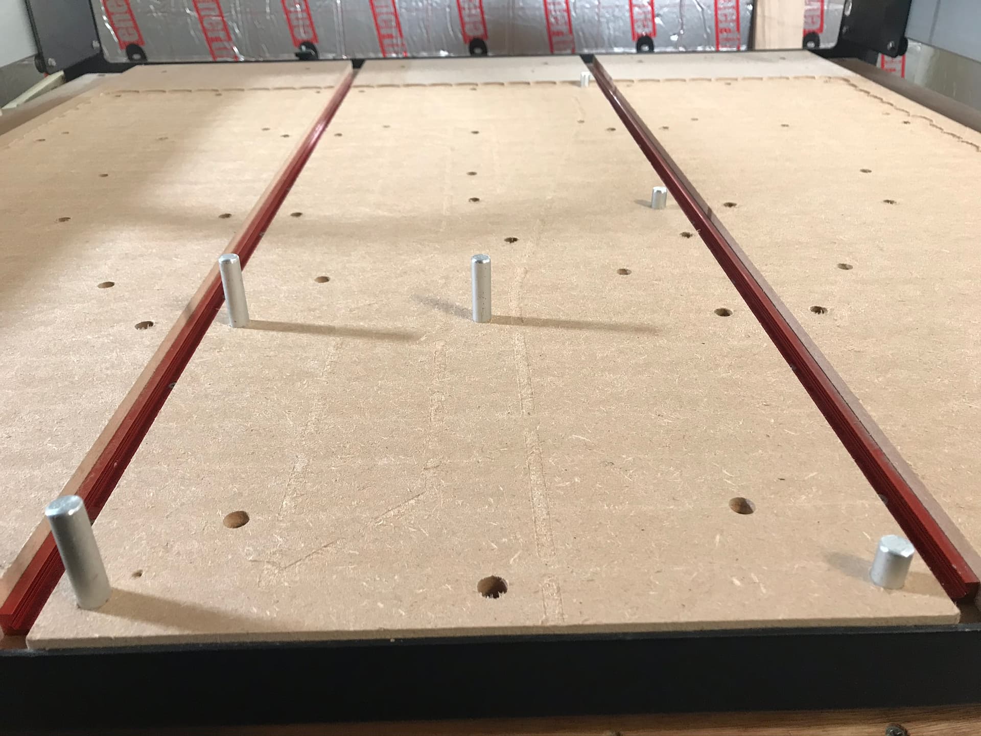
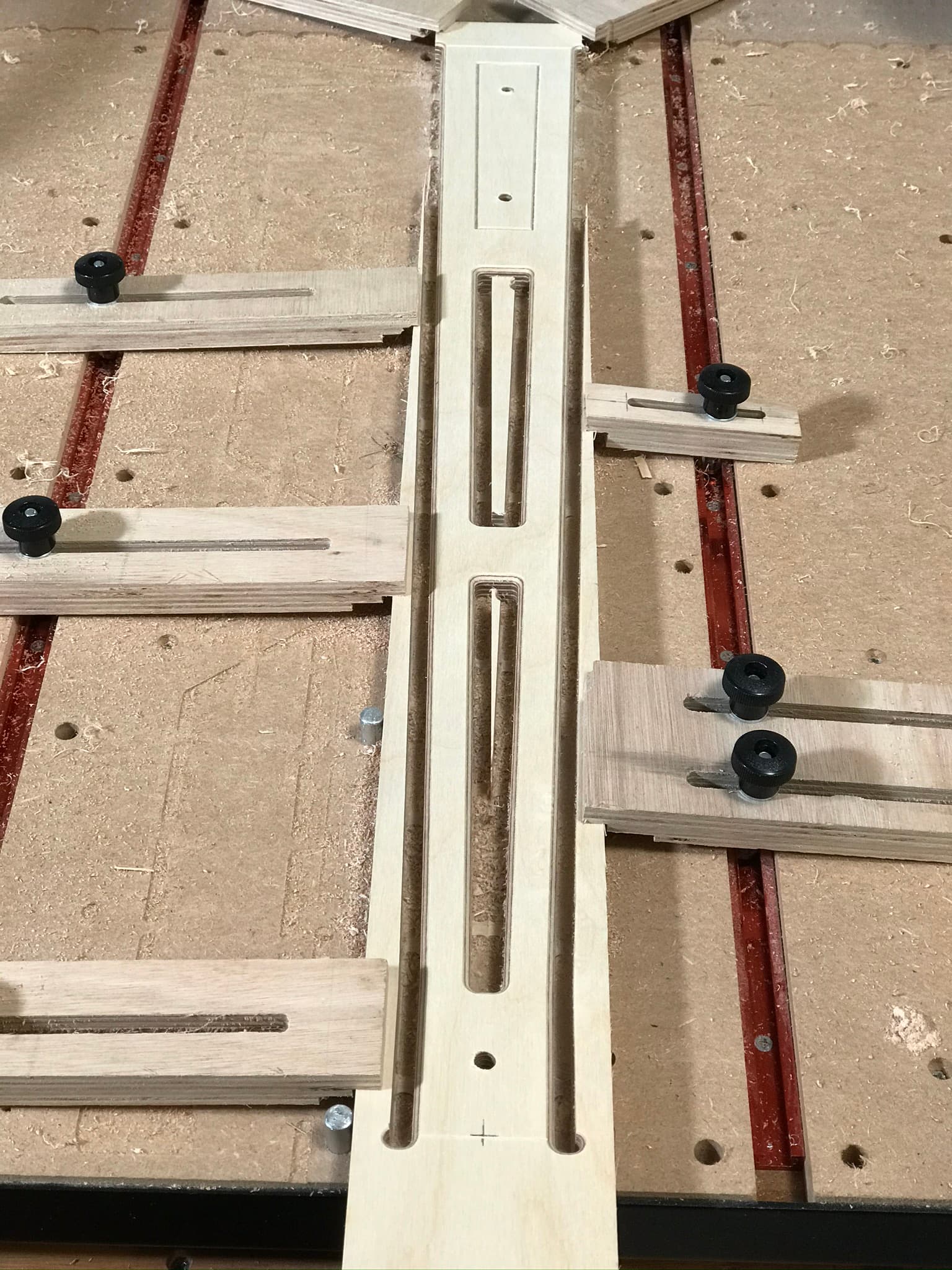
On my only other tiling projects I set up a fence along the Y axis and machined it parallel as a reference surface, then by making pencil marks on the fence and workpiece I VEEEERY carefully slid the workpiece down 736.314159265mm. This proved to be super time consuming and stressful. This time around I thought registration dowels would be a great experiment. Spoilers: WORLD OF DIFFERENCE.

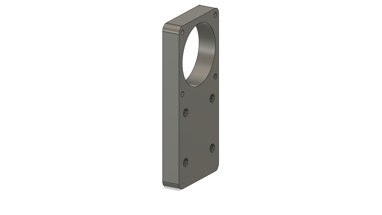
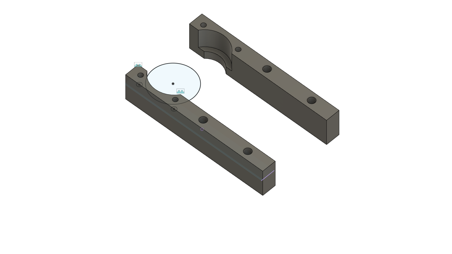
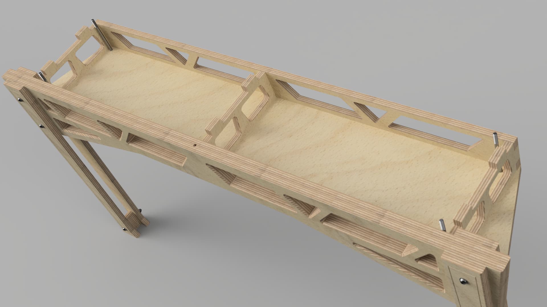
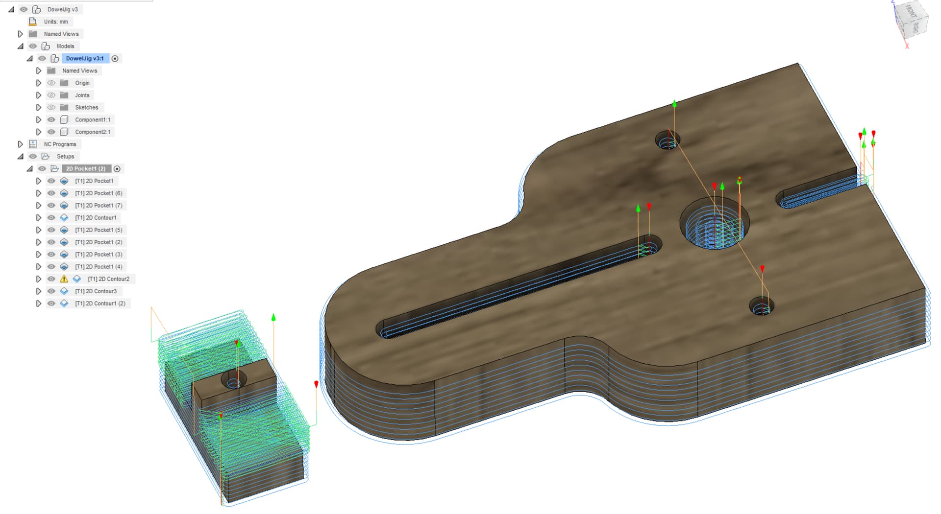
Having no plywood on hand, having just picked up 1"x10"x14’ pine boards and no reason to make ANOTHER trip to the store, I decided to double down on things I’ve always wanted to make and created a dowel centering jig. So this will be a two for one build post. Here is the design I settled on after a quick google image search.

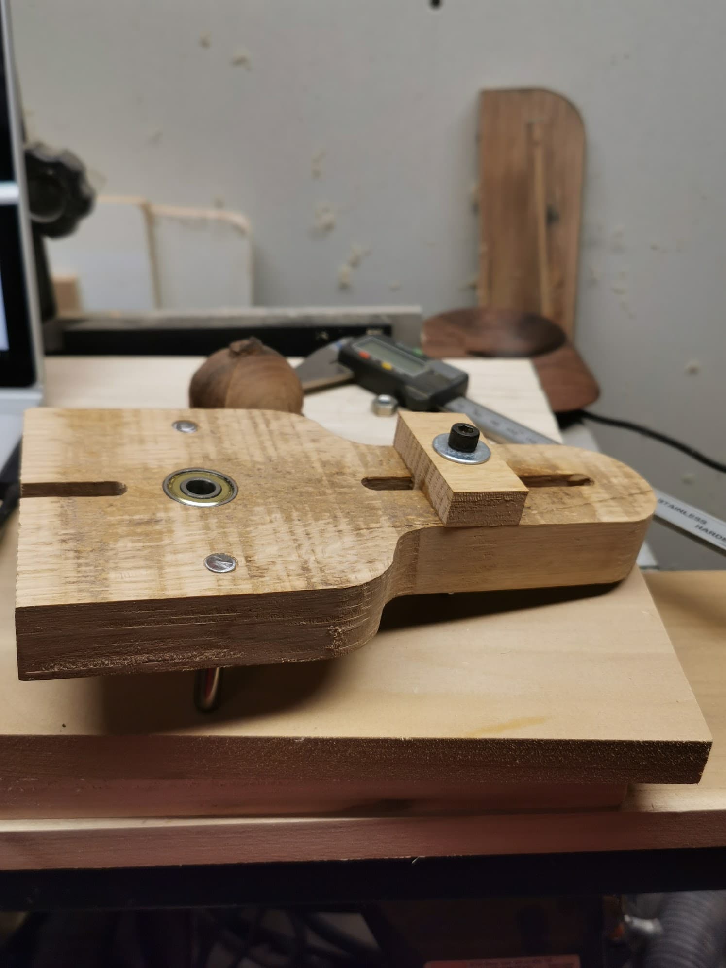
All the materials I had laying around already, the white oak was an off cut from a cabinet maker acquaintance, bearings were extras from when my dad was into roller blades (so the standard 8x22x7mm shielded bearing), precision ground 8mm steel shafts from an old printer I tore apart ~3 years ago.

After reading the below thread:
boring-a-round-hole-without-a-taper/36415

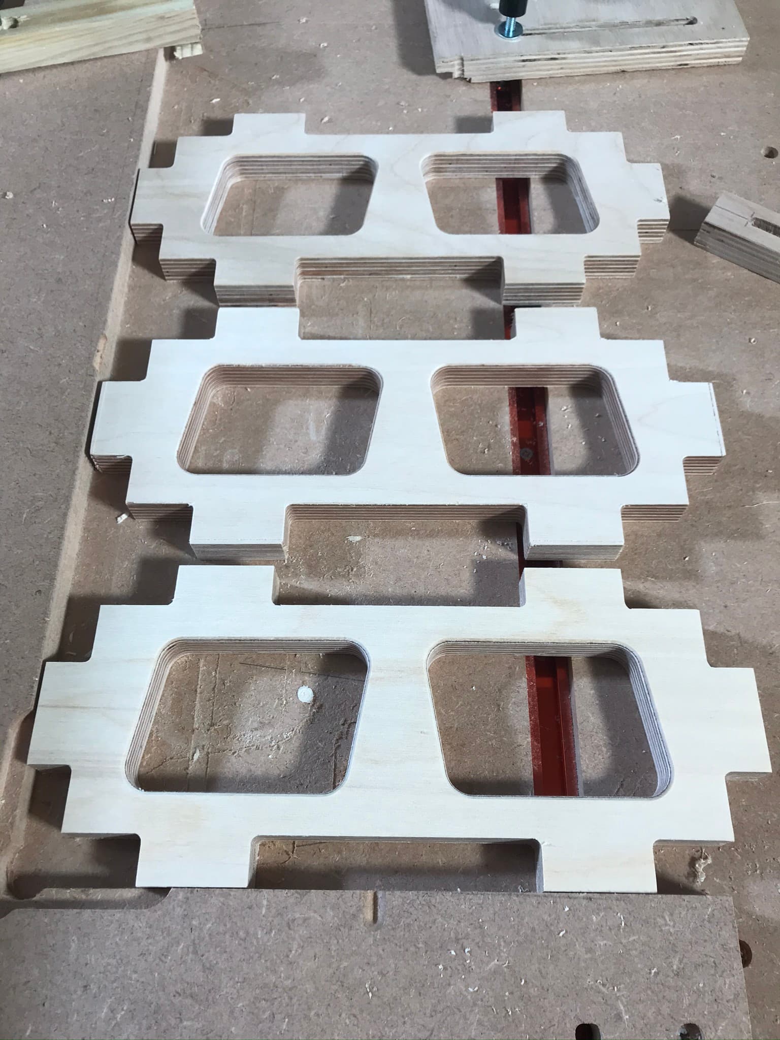
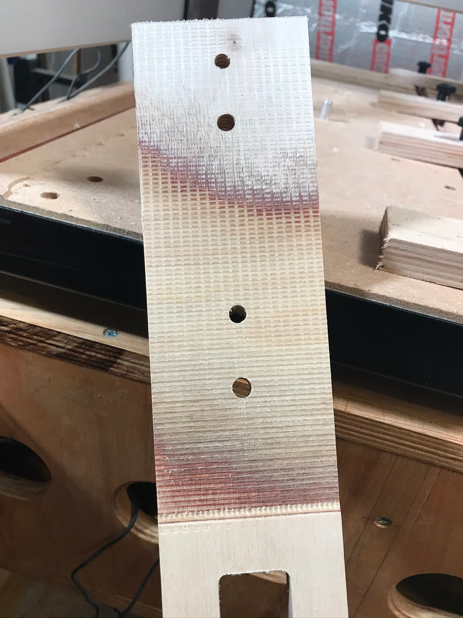
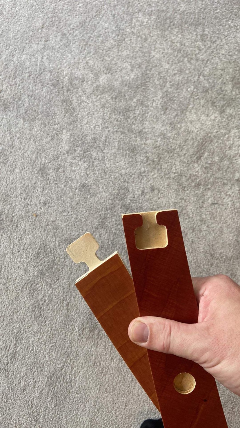
I didn’t think it possible to machine an 8mm pocket with tight tolerance through 1-1/16" white oak. But after playing with Radial Stock to Leave and a Contour Toolpath, the holes for the locating pins was perfectly sized, a quick chamfer on the steel dowels and tap,tap,tap the jig is basically complete.

The keen eye will see that the slots dont come close enough to the center of the drill hole. which lead me to get creative with the second set of holes.

Here is the Cutrocket link: Dowel Centering Jig by TysonD

All set, or so I thought. If only I had a complete set of drill bits instead of multiple incomplete used/discarded sets dating back 30 years, not to mention there is no chance any of them are metric. Luckliy a 5/16" (7.94mm) twist drill bit with positive depth control is a beautifully snug fit.

Next step is to use the dowel jig!
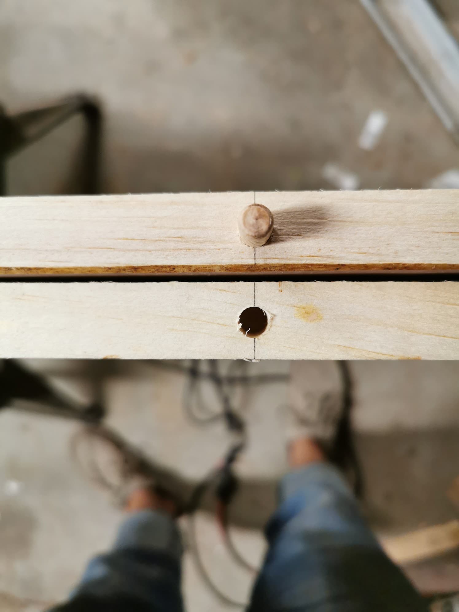
I decided on 1 foot spacing between dowels. Which is retro spec was a little too far apart. Remember when i said “get creative with the second set of holes” Things were JUST off perfect.

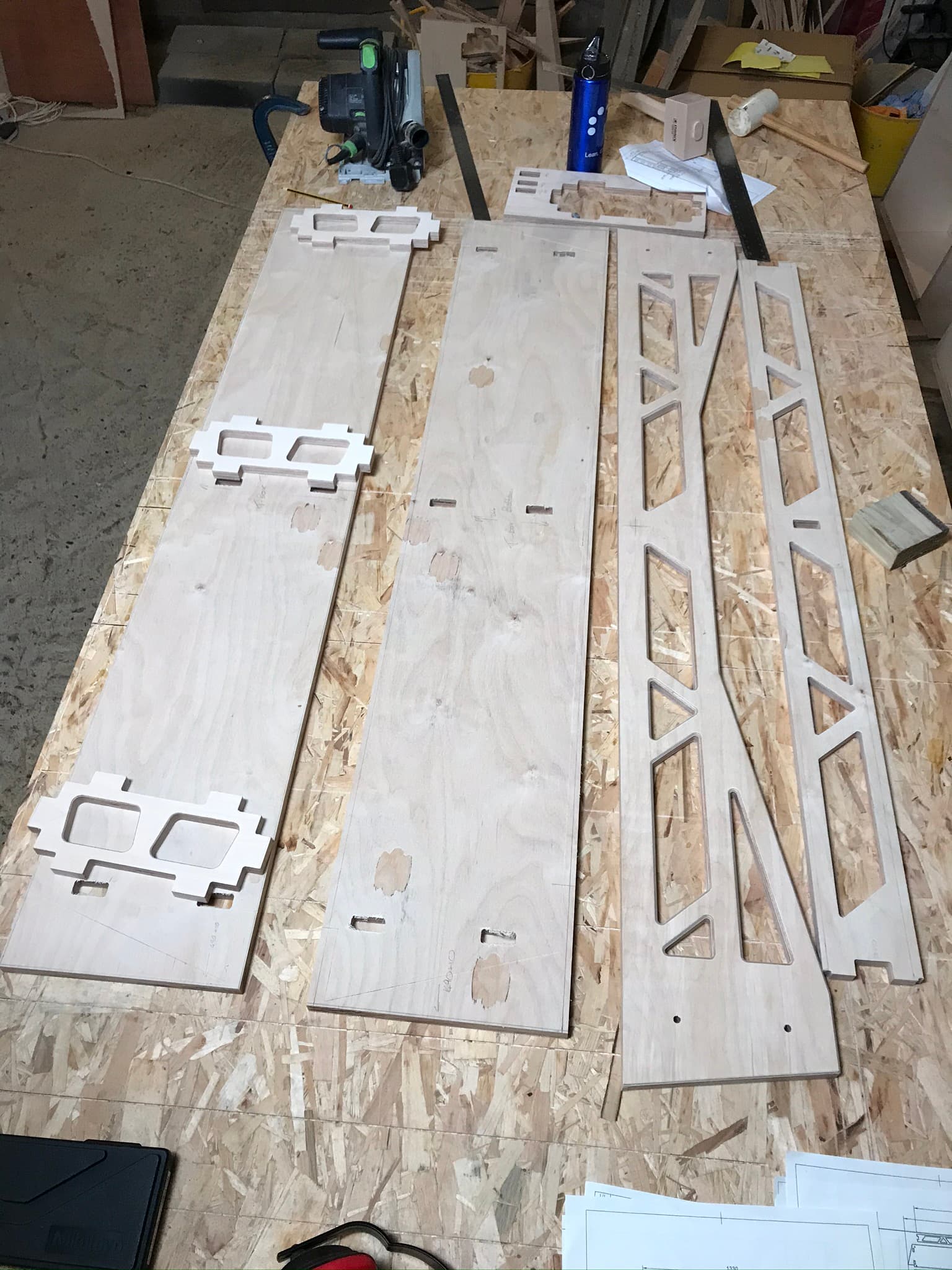
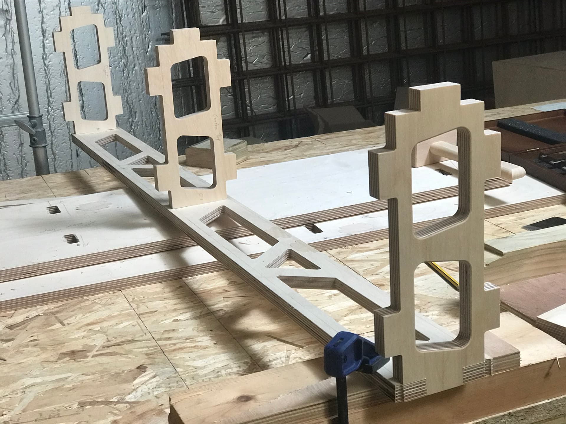
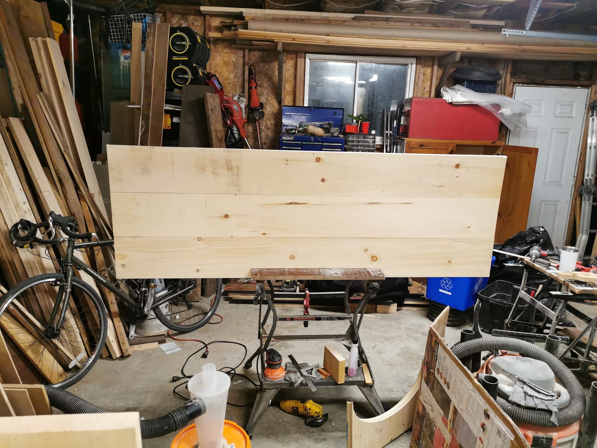
Success! Dry fit passed

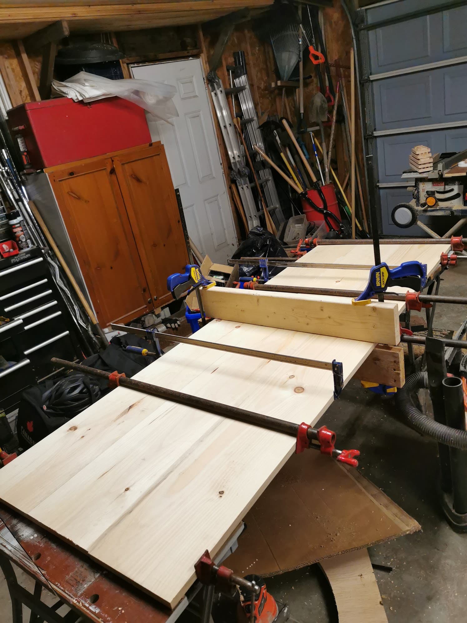
On to lamination. It was kind of rushed and halfway through I realized how crucial cauls would be. But it turned out well.

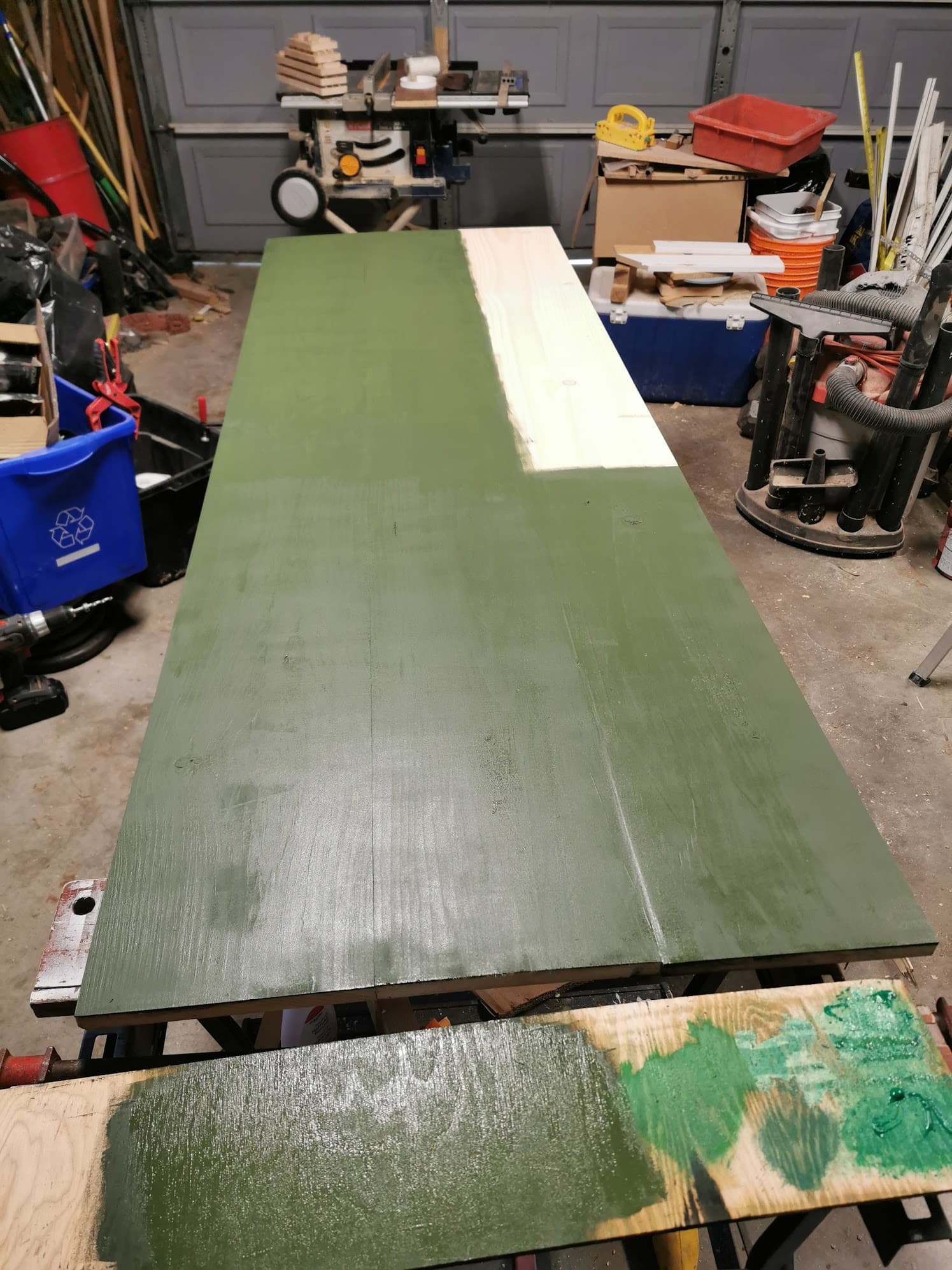
After scrapping off squeeze out and 10mins with my ROS using 180grit, it was time to paint.

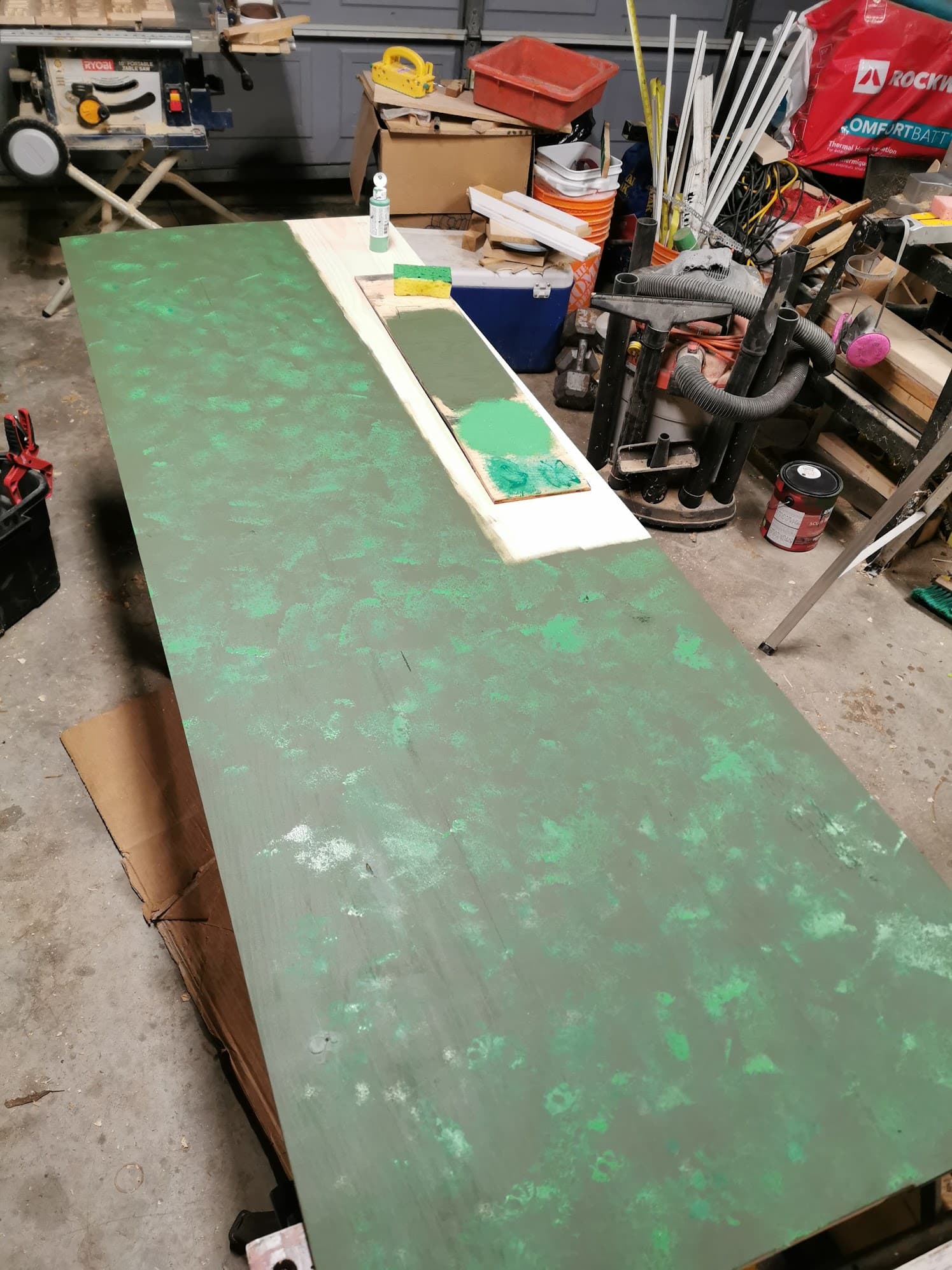
Behr River Forest base, dollar store green and shiny green sponged on to to achieve texture/scales/camo lol, it’s simple but I was pleased with how it turned out.

Now is where I change gears and write two macros to easily switch between by Dewalt Router with 1/8" collet to and JTech 2.8W laser. I chose to do it this way because I figured it would be beneficial to watch the machine move into place rather than use the G54 offset options. However I will revisit these for a better understanding.

Router to Laser

%
ORouterToLaserAbs
G90 G21 G53 G40 M5
(M01)
G00 Z10 (Clearance)
G00 X0 Y0 Z10 (Return)
G00 X-73 Y86.0 Z7 F2000 (From Router to Laser)
G01 M3 S1000 (BLAST LASER!!!)
G4 P0.5
G01 M5
G10 L20 P1 X0Y0Z0 (Set current position as origin)
(M01)
(G00 X0 Y0 Z10 (Return)
G00 Z7 (Tool atop workpiece)
G90
M30
M5
%

This is the moment my Rpi that lives in dust city next to the machine becomes SUPER unreliable. (Which I’ll have to make a separate post about just get to the bottom of.) So I copied the macros into text files and loaded them for tool changes. Slight inefficiency but it still works.

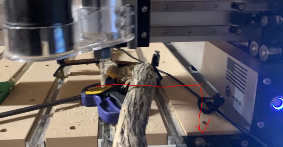
There were many considerations to make when keeping the laser attached to the carriage the whole time for efficient tool changes.

Laser focal length ~40mm
Keeping the end mill safe while lasering (min 2mm clear above tallest clamp)
thickness of material 20mm
Height of collet vs lowers point on laser
Large work envelope in XY plane, can the laser and router reach all features?
Were did I have spoil board meat to support a 8mm dowel

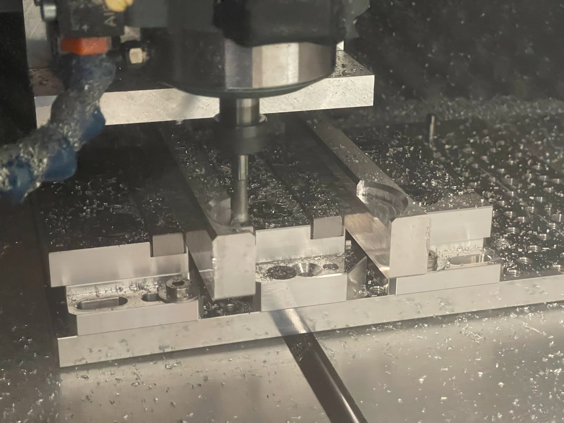
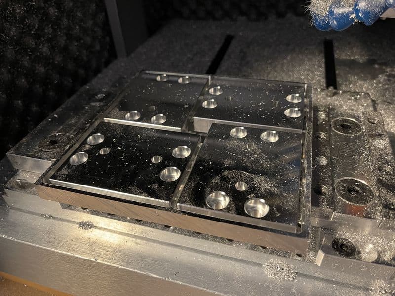
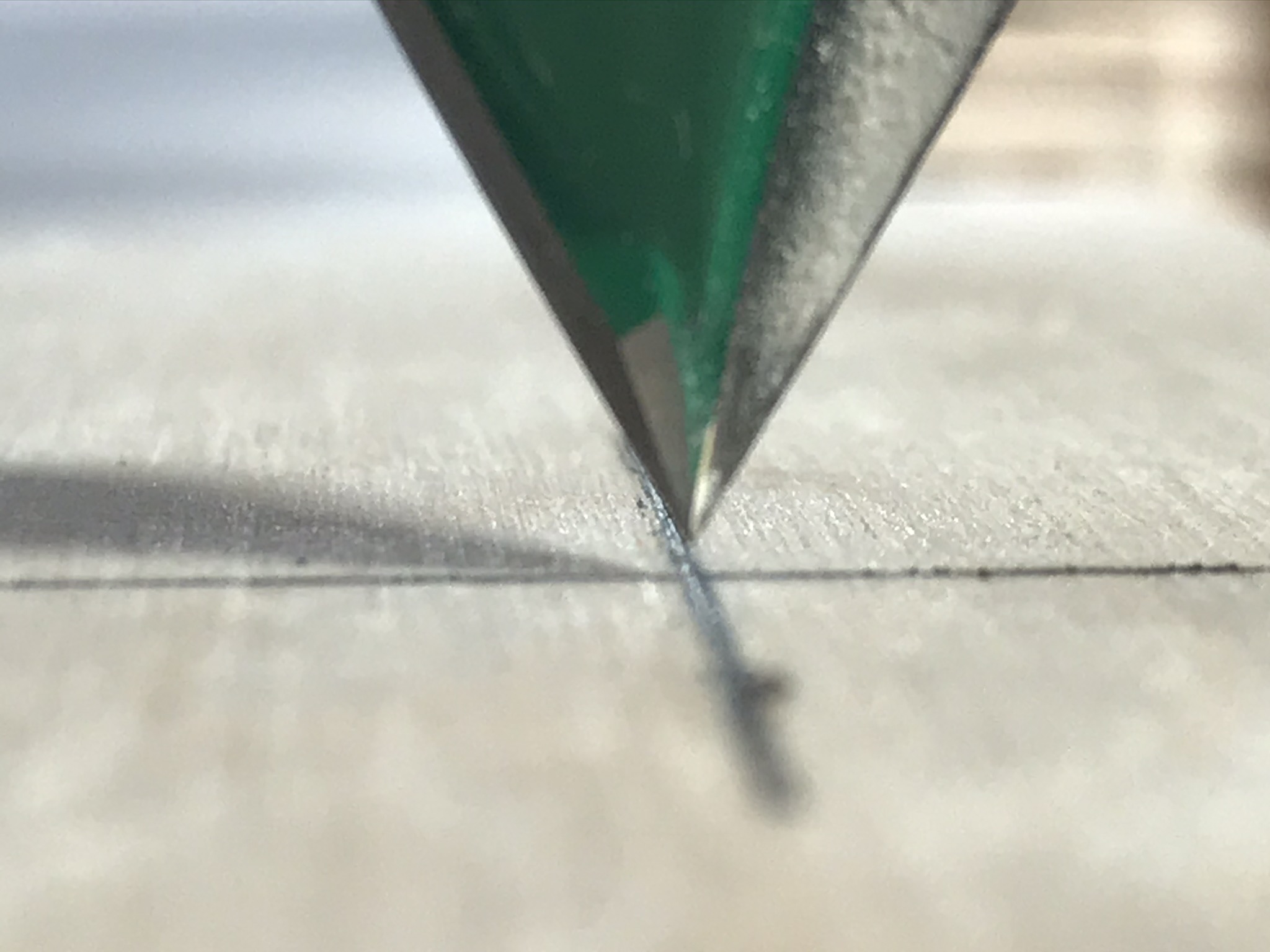
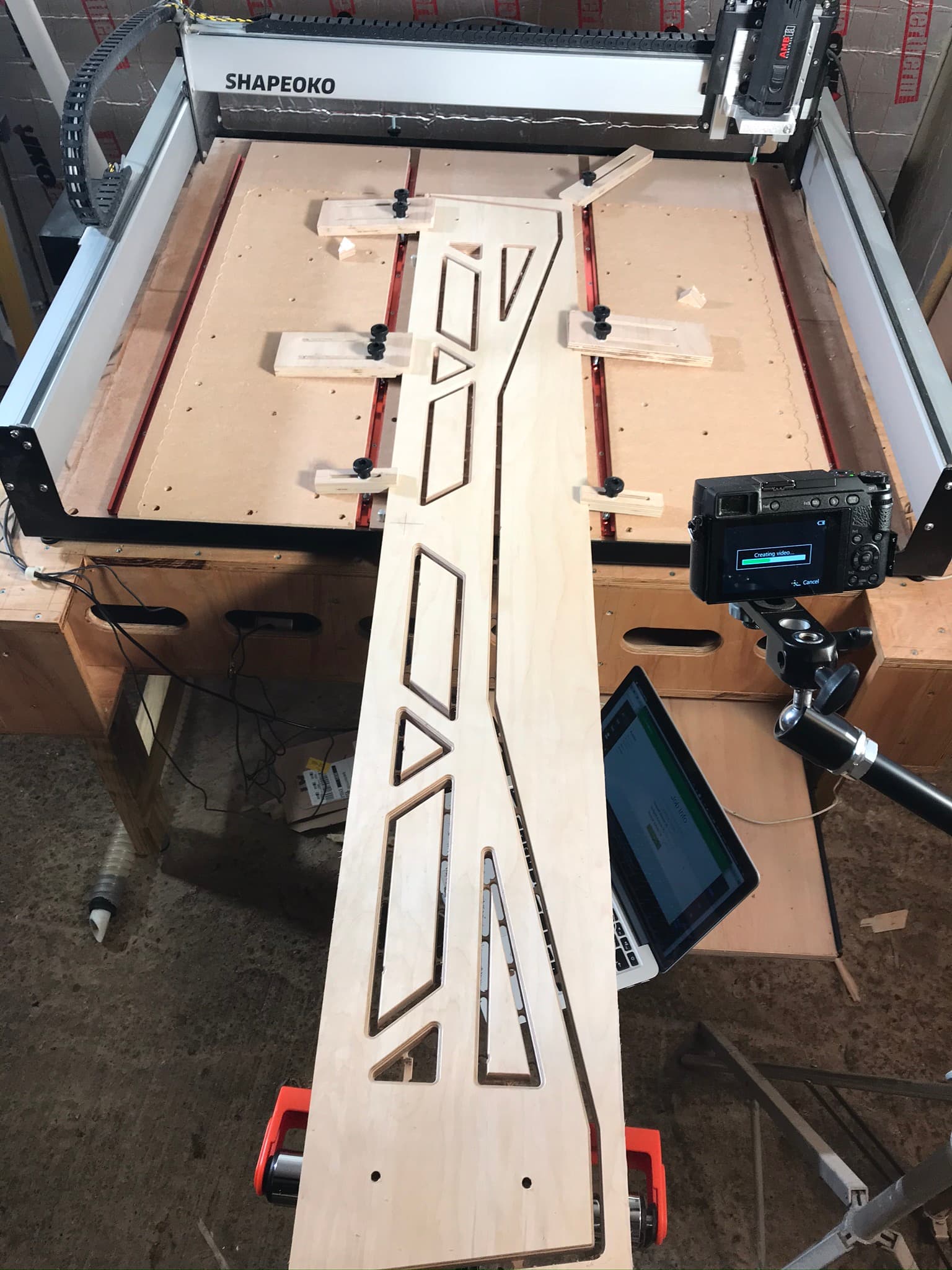
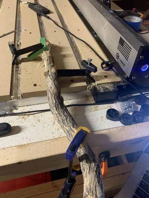
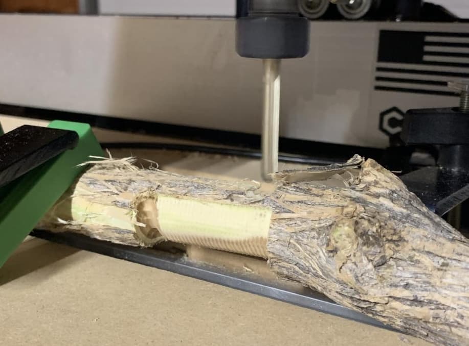
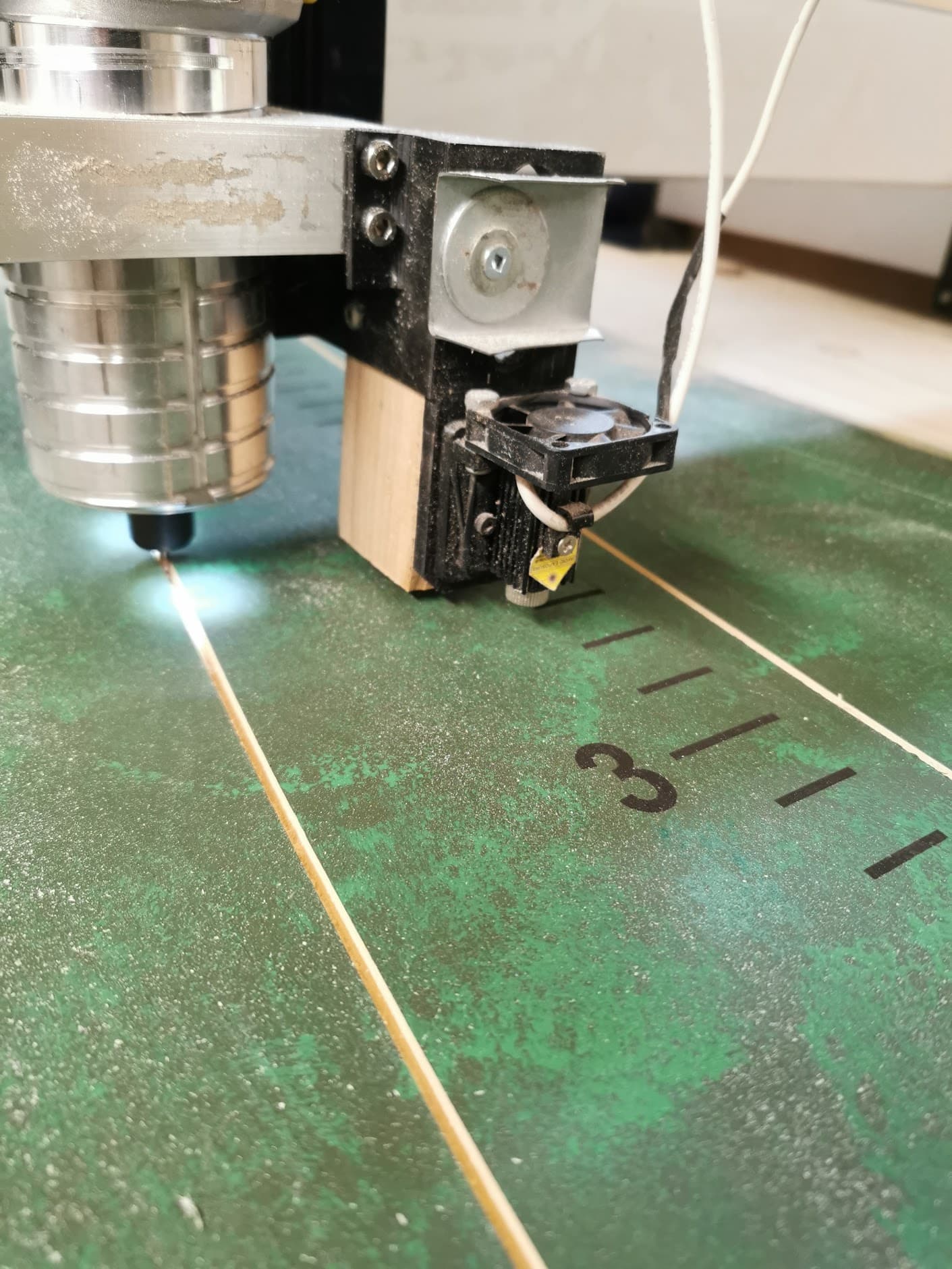
Because of this it took 30mins to finally set the origin point on my XXL table. The video below is the clearance the laser gets while drill the locator holes.

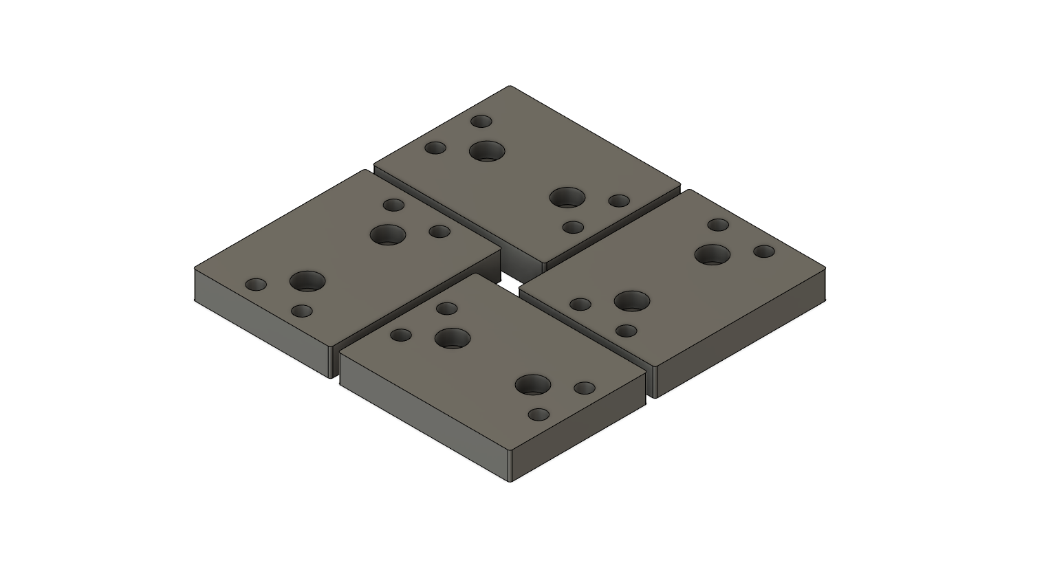
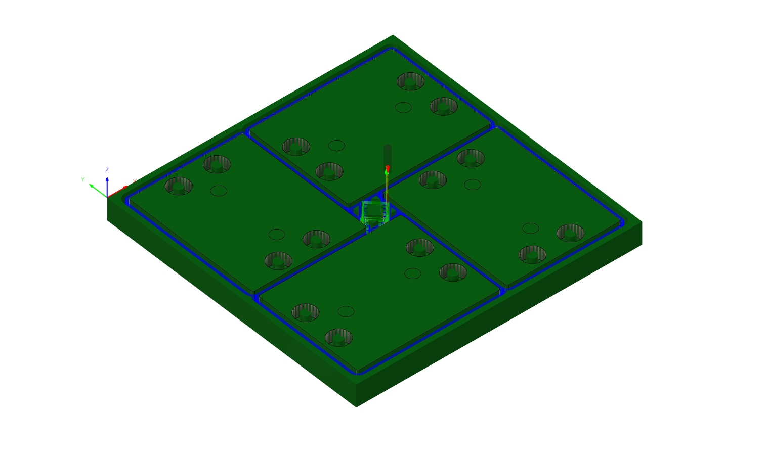
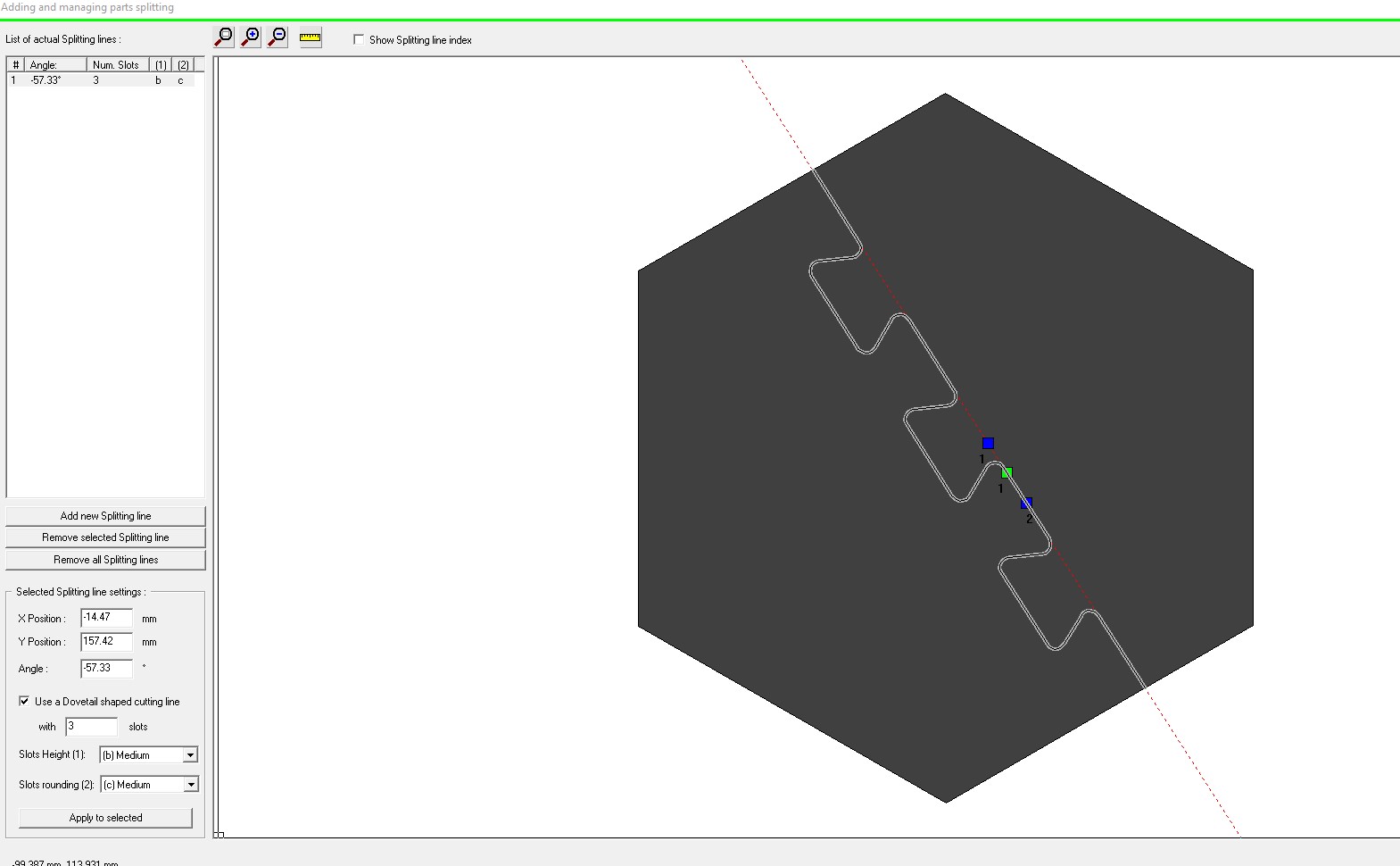
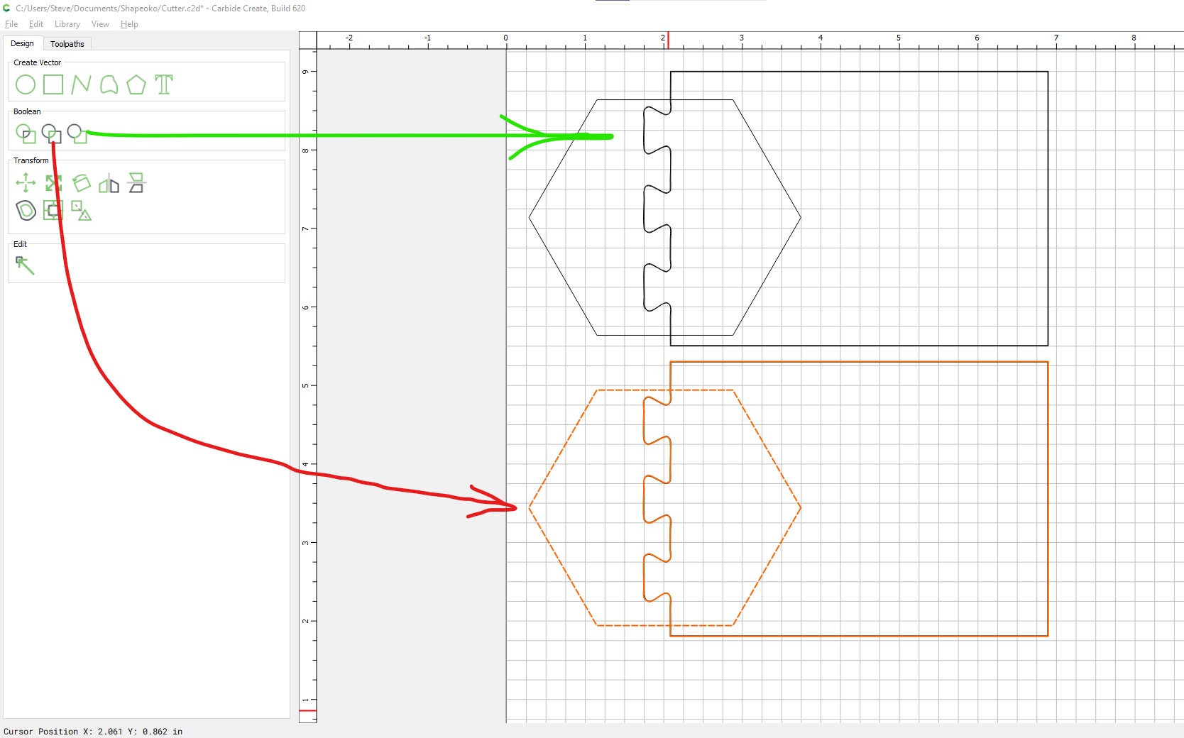
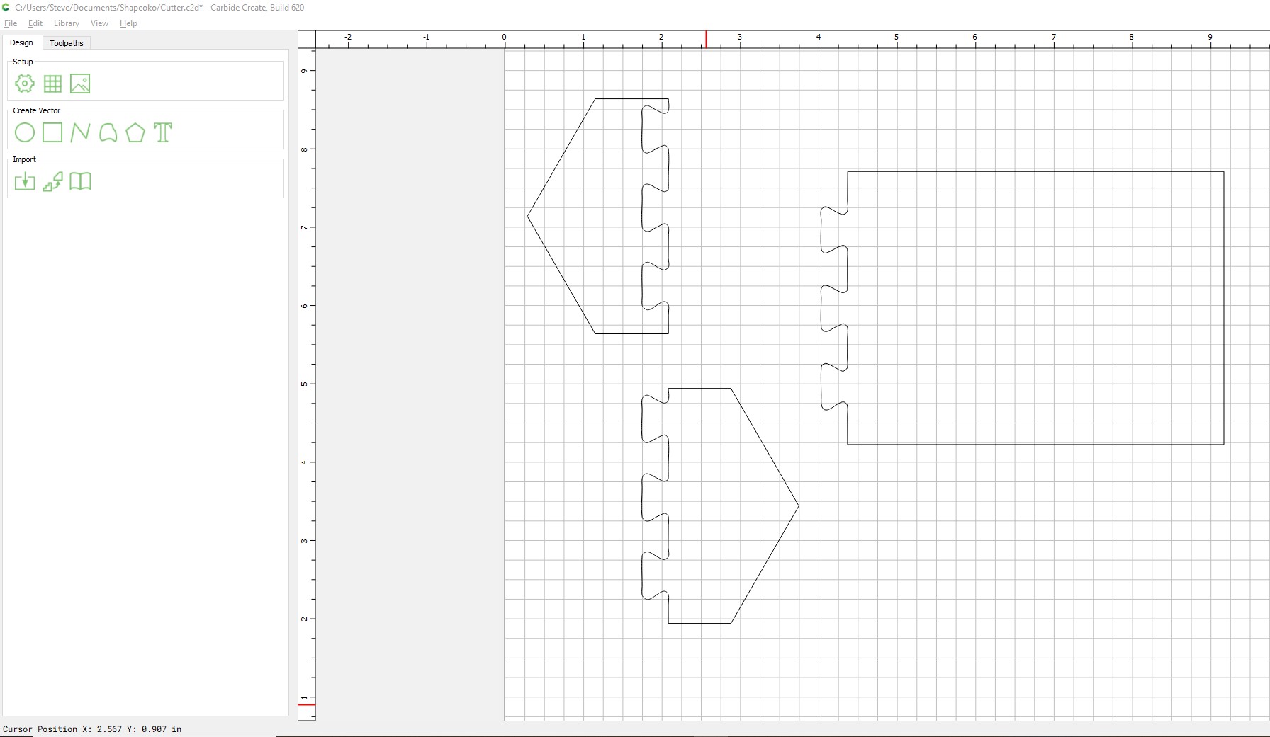
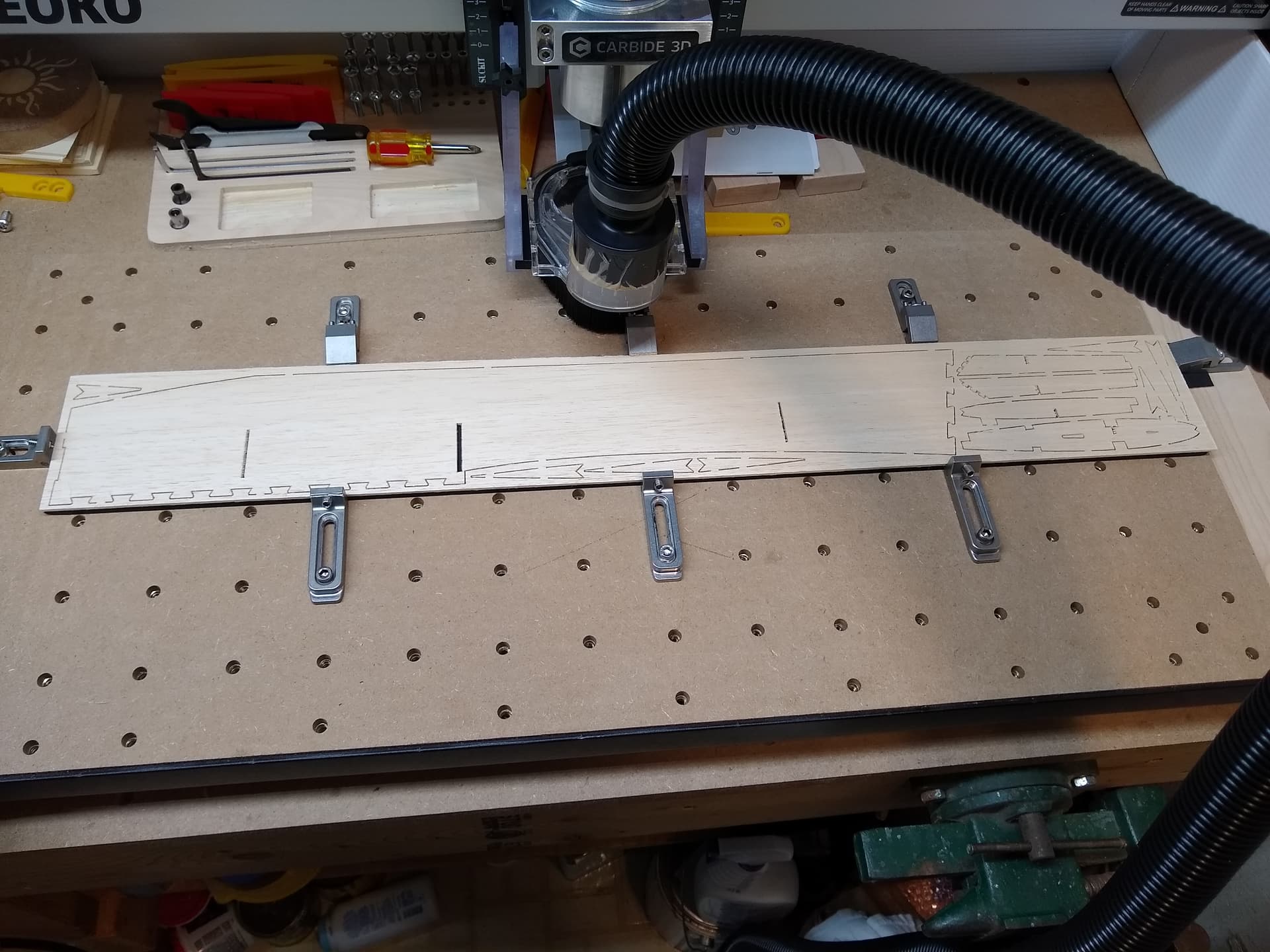
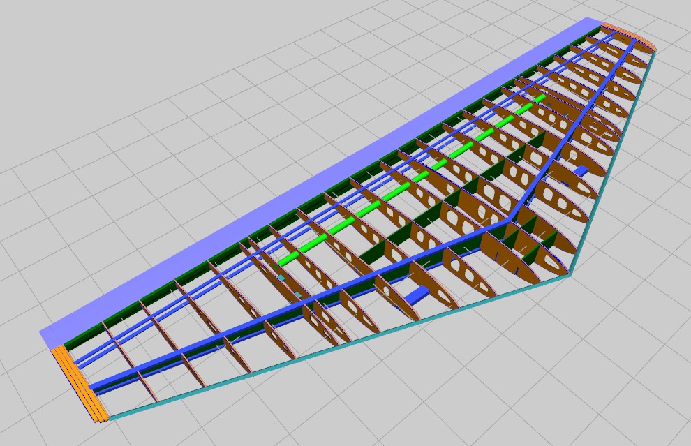
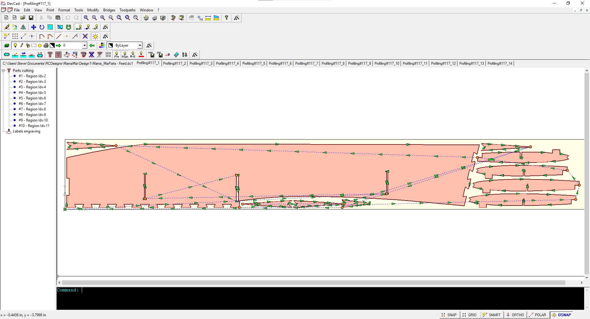
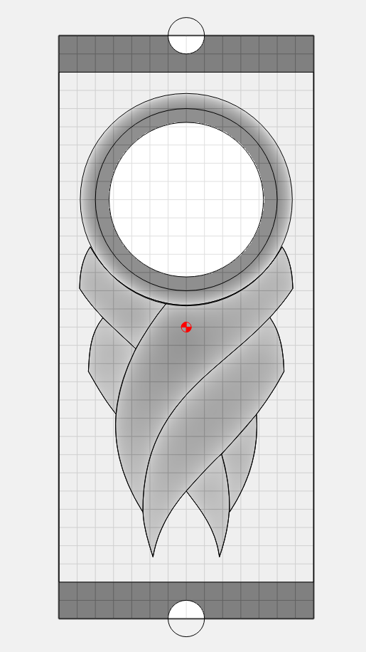
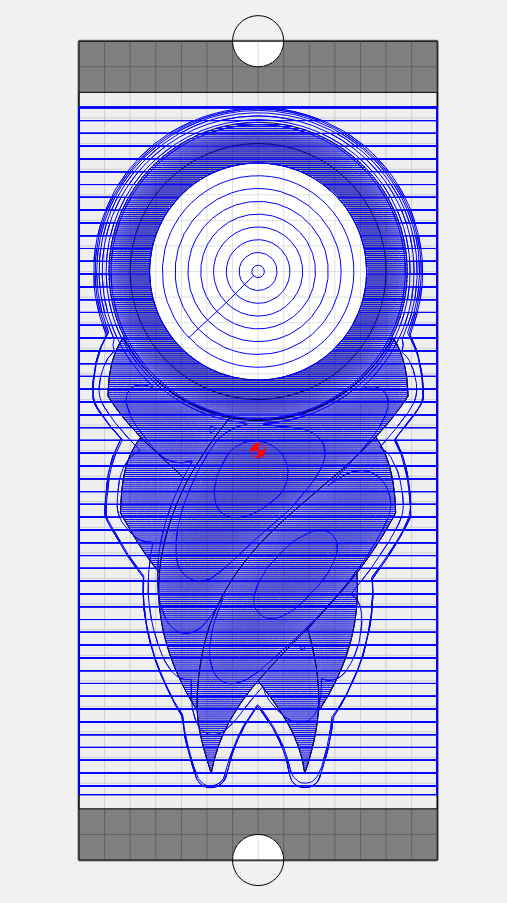
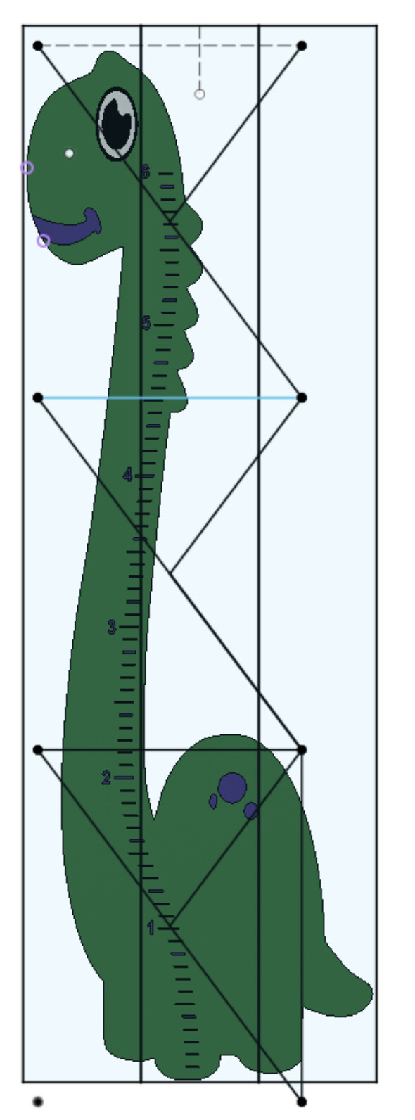
The job is broken down into 3 setups, This is the first time I’ve had features continue through a tiling boundary, so this was the test where dowels could REALLY excel. I used a sketch to plan out where the model would be cut out of the stock, placement of locator dowels. Used the lines from the sketch to create construction planes to then split the body, forming perimeter lines broken at the tiling boundaries which I could select using the ALT key in F360.

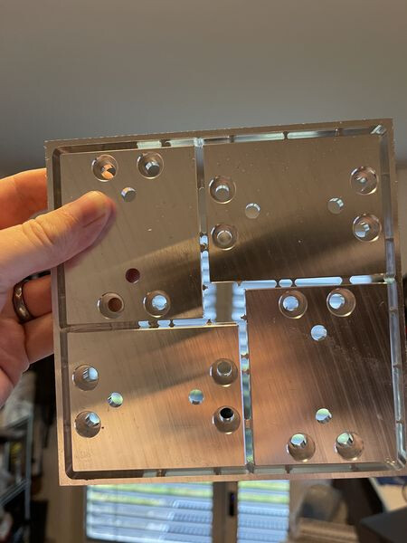
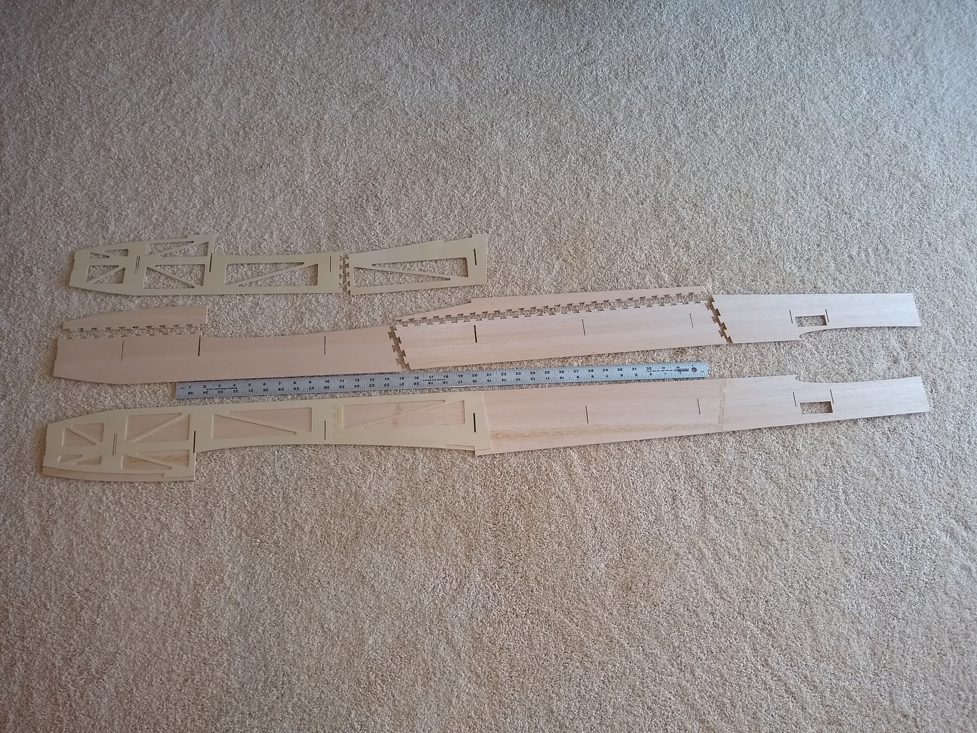
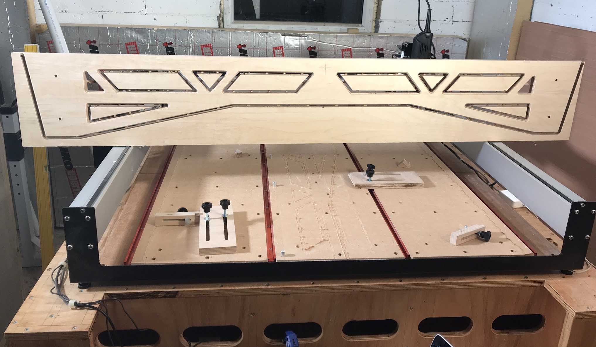
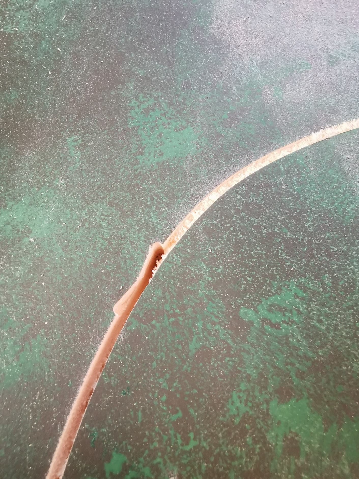
Invisible transition between tiling sections, looks like there is something to this method. Small 4x4 triangular tabs hold the dino in place as the profile is cut out.

I like to play it close like my name is Glenn. Lasering went off without a hitch 1350mm/min @ 36% power. It left a very fine, deep but soft black char on the wood paint. This will later get sealed with either poly or shellac.

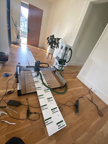
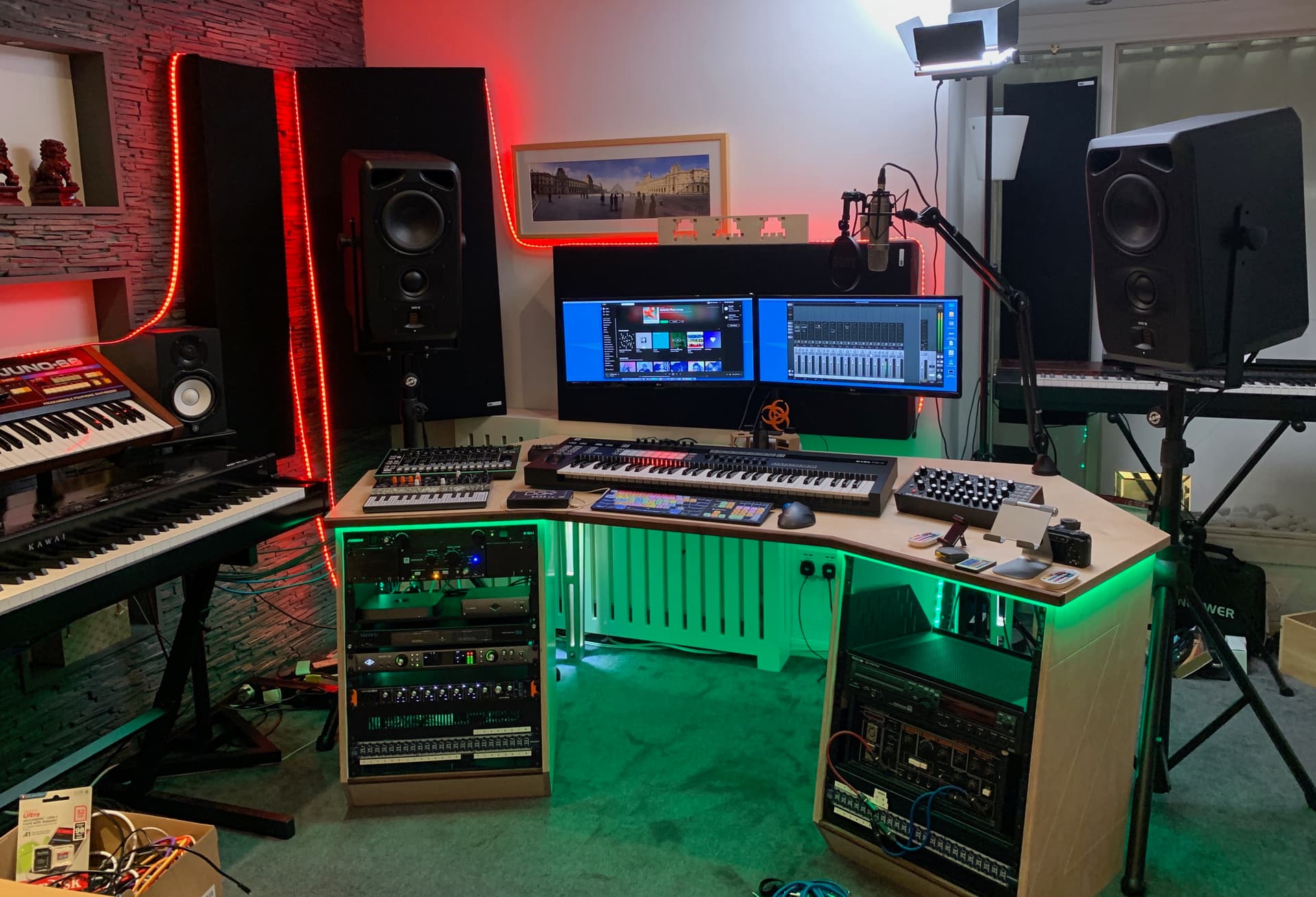
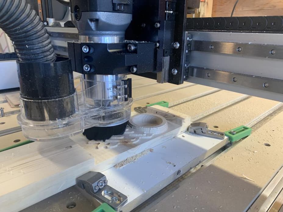
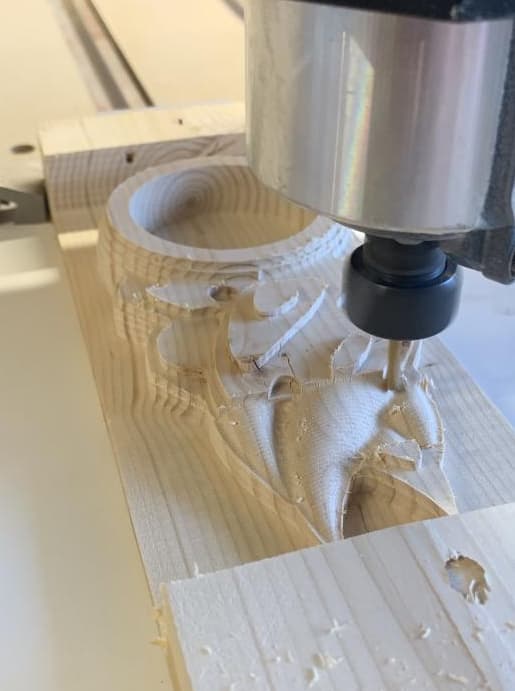
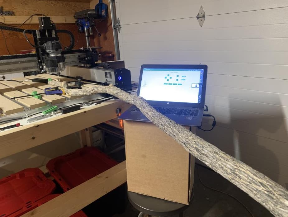
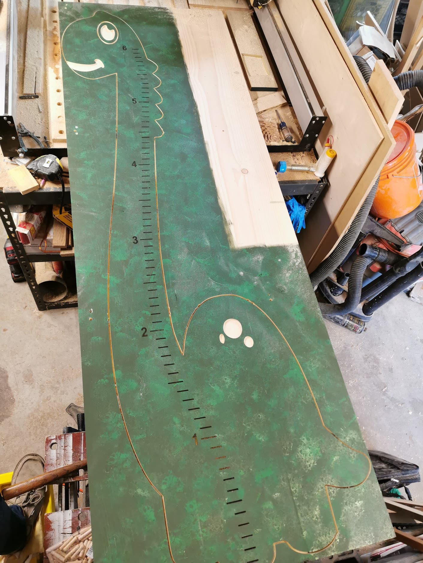
It’s coming together! Oh yeah this is my shop.


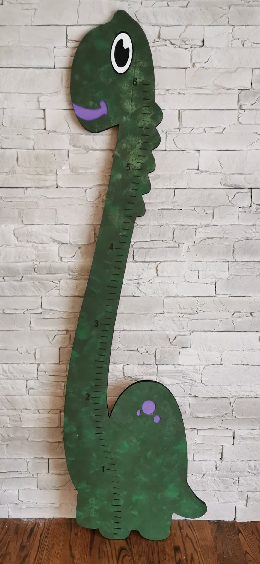
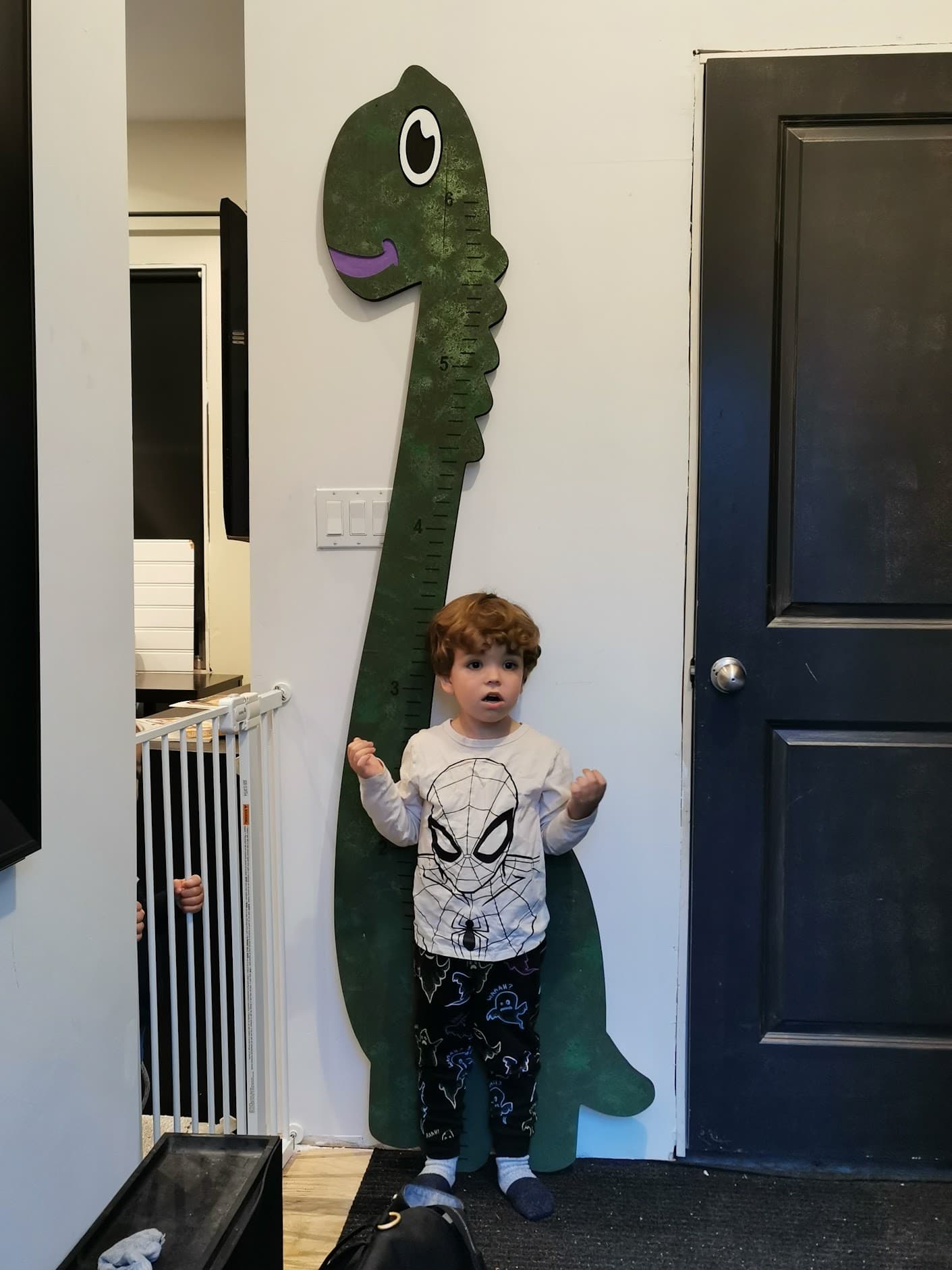
After some acrylic paint. It is finished!

Unfortunately little munchkins are just getting over colds so I couldn’t make a production of picture time.

Cutrocket file to follow.

Lesson’s Learned:
Paint highlights imperfections in sanding
Dowel joinery is pretty dope ( must test lamination strength)
Four Locator Dowels seem to be a superior tiling method (tests to be done as a flip jig)
Router to Laser tool changes aren’t difficult and open up many designs/details.
Downcut bits retain enough sawdust to relax the need for tabs

20 Likes