Using "Advanced VCarve" in Carbide Create 461 to make Inlays

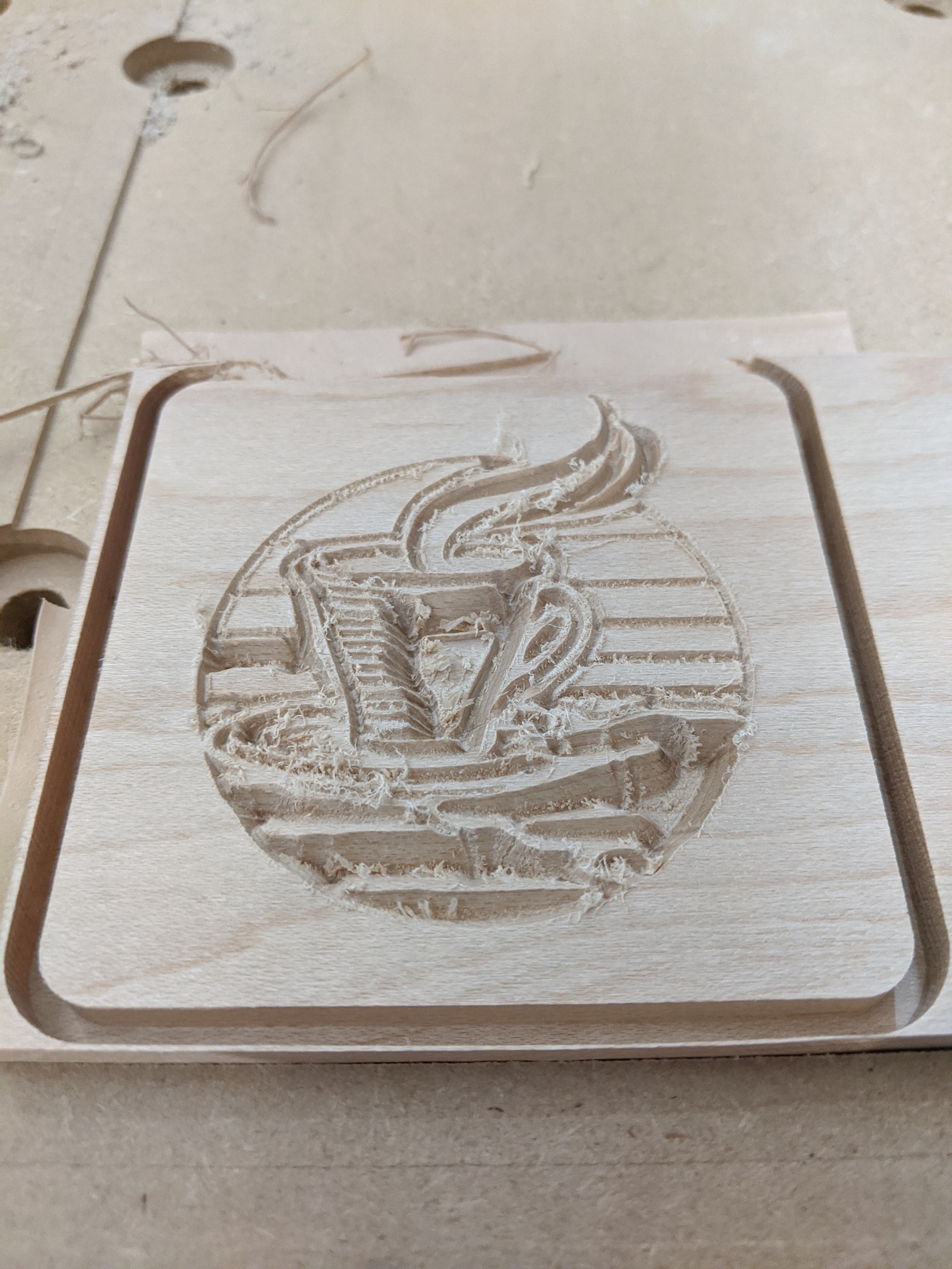
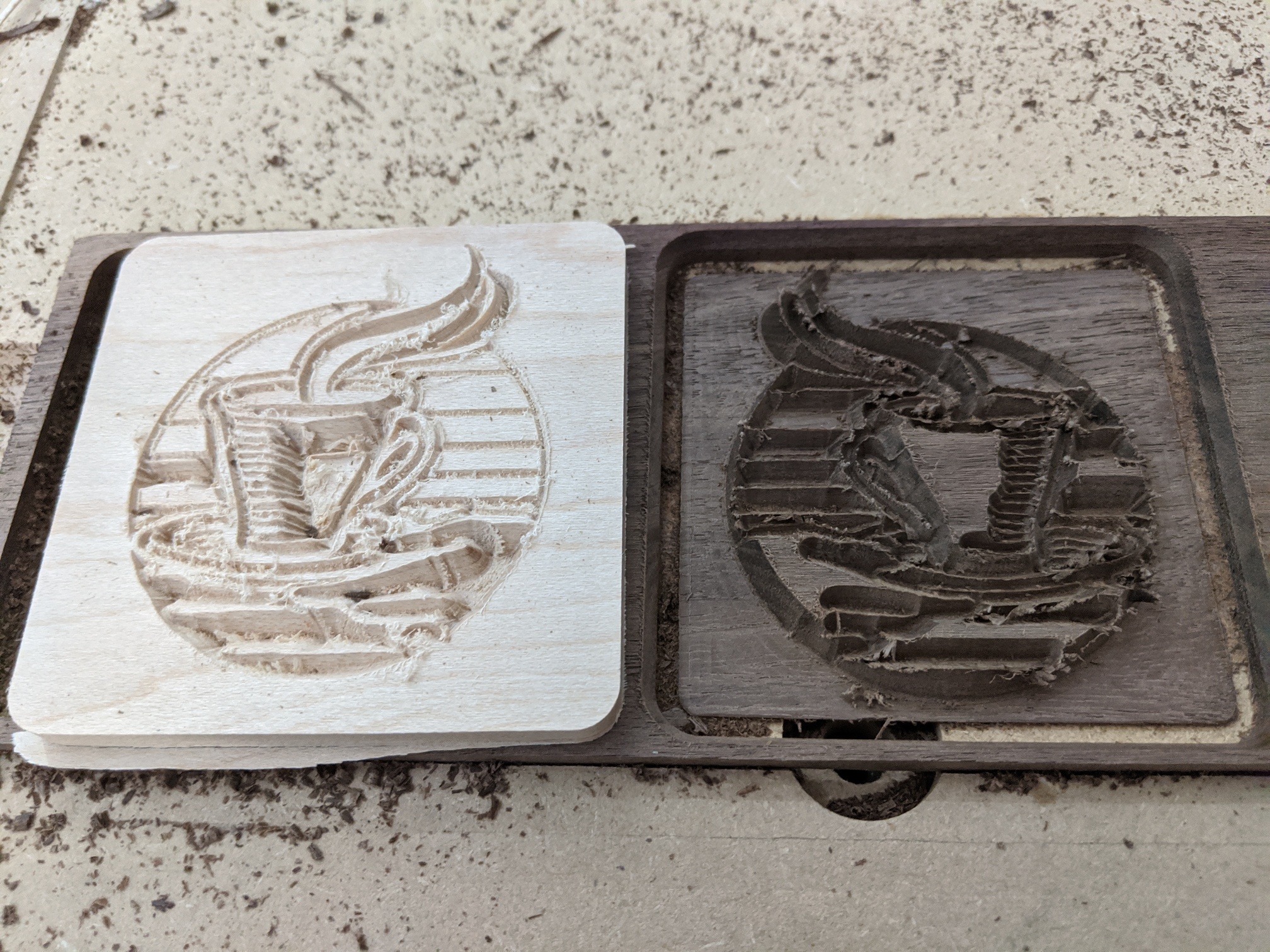
Now that Carbide Create has the advanced V-Carve feature, it has become possible to make inlays (see picture above).
I’m going to go through the steps I used to make the coaster.

(Update two weeks later: I am learning that the smaller the angle of the V bit, the better this technique works. 90 degrees… don’t bother. 60 maybe… 30 gives much better results)

C2D files: coffee inlay tutorial - inlay side.c2d (624.7 KB) coffee inlay tutorial - coaster side.c2d (449.1 KB)

Steps 1 - 5 are designing the base for the inlay

Steps 6 - 9 are designing the “plug” that goes into this base

Steps 10 and later are describing the machining phase

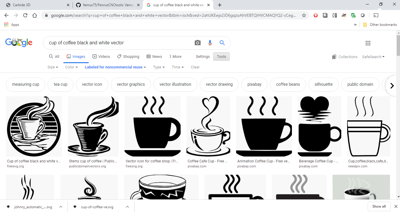
Step 1: Select the image you want

Google Image search is a great resource for free SVG files:

Step 2: In Carbide Create, set up the stock


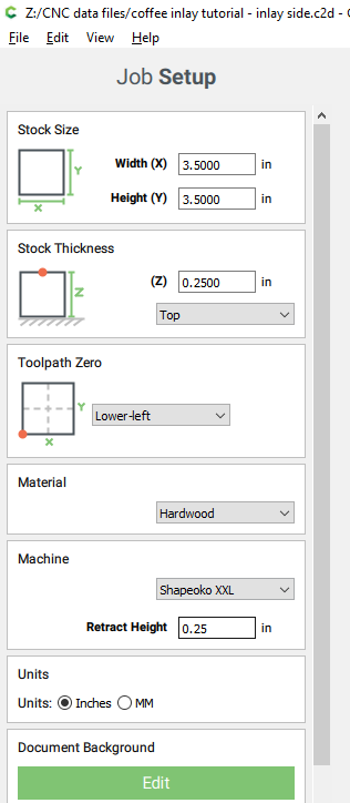
I’m using a 3 1/2" x 3 1/2" x 0.25" piece of stock, so I put those dimensions in.

Important: Make sure to set the retract height here at least 0.125" higher than you normally would, setting it to the thickness of your stock is a good convenient value

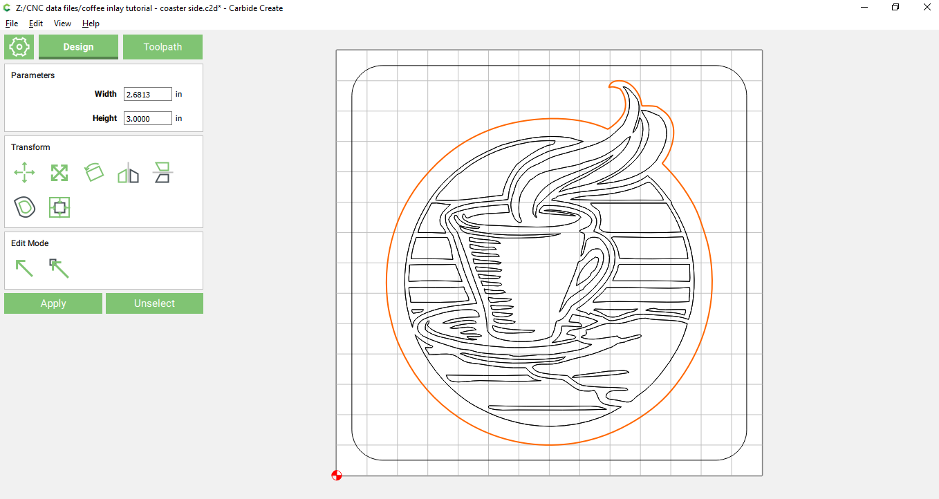
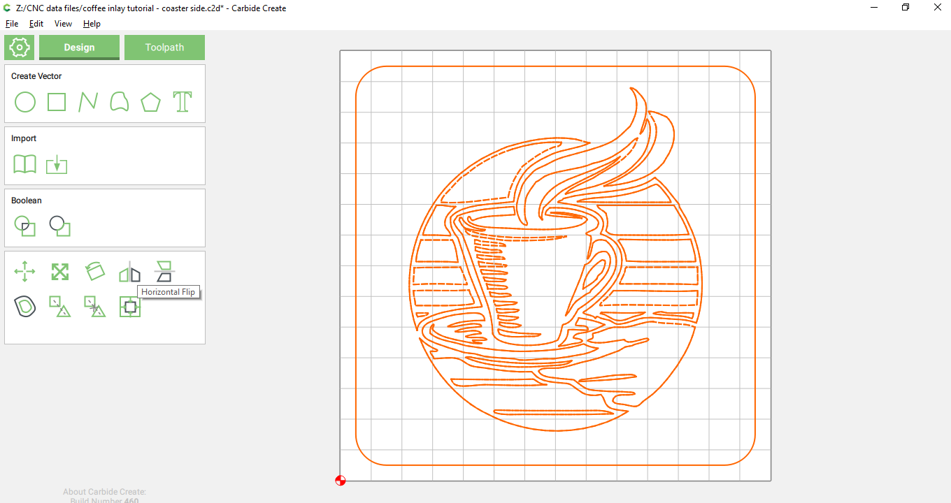
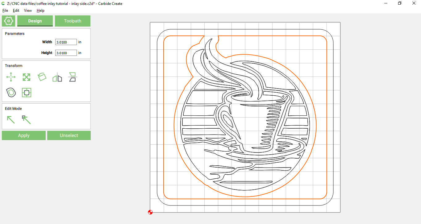
Step 3: Create the Carbide Create design


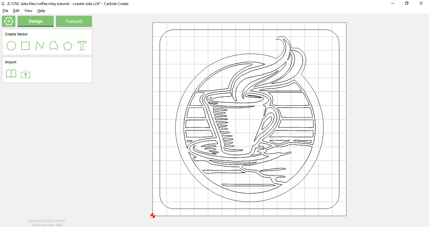
The design SVG has an extra border around it that I did not want, so I deleted it

Step 4: Toolpaths
The cutout using a simple outside contour:


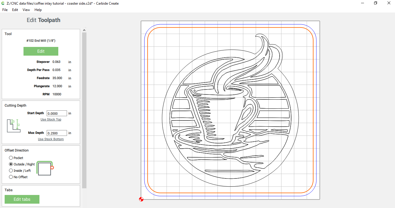
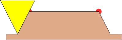
And the coffee cup using the new advanced V carve feature:

The 0.2 depth is important (you’ll see later why)
As @CrookedWoodTex points out in a post below, the 0.2" is very conservative and can lead to a hollow part in the final. Once you are comfortable with the process, you can reduce this to 0.15" or even 0.125". This will leave less space for glue, but also leaves less of a hollow in the final work.

Step 5: Preview & GCode saving


After checking the preview, I saved the gcode for this toolpath

The following steps are switching to creating the “plug”. It’s a good idea to save the design here, and use a separate file (save as) for the second half of the process.

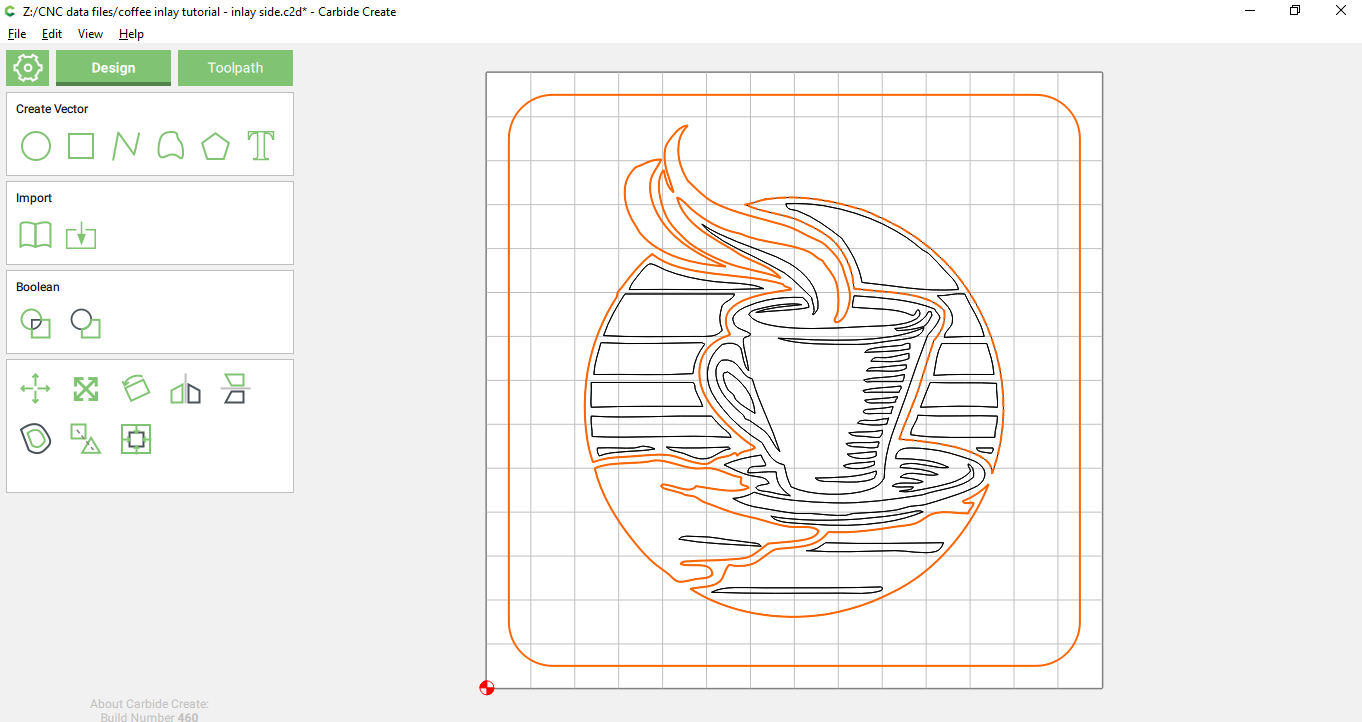
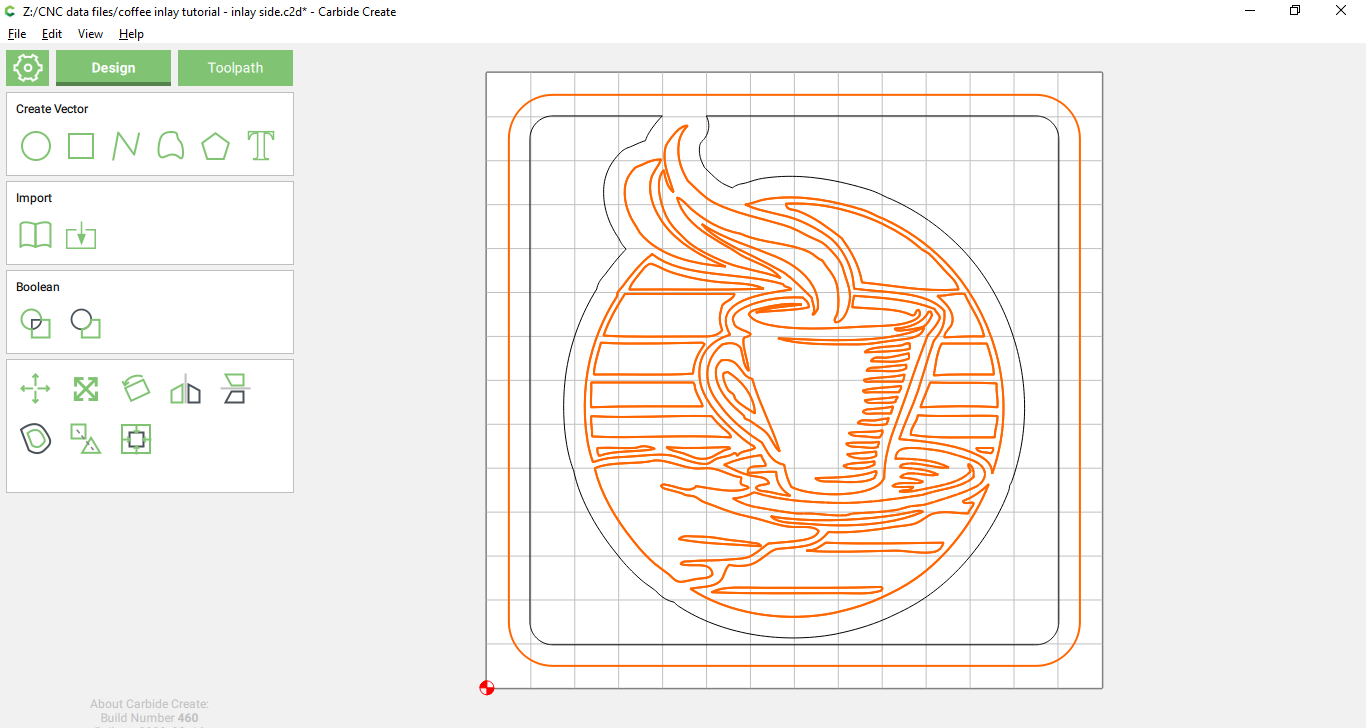
Step 6: Mirroring the design
Since the plug will get inserted “upside down” into the base later, we need to use the “horizontal flip” feature of Carbide Create to swap left-to-right:

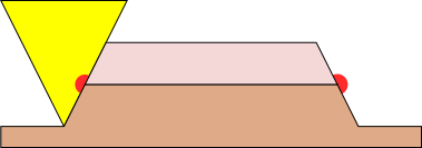
Step 7: Create a roughing pass
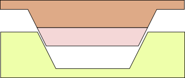
It’s a good idea to use a roughing pass, and in order to do this, we first create an offset path with an inset of 0.12" like this:


and then we pocket this new geometry to a depth of 0.2":

Not shown in this screenshot is that I also created a cutout toolpath similar to the path created in step 4, to be part of the roughing step

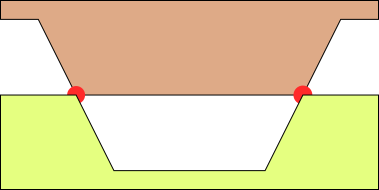
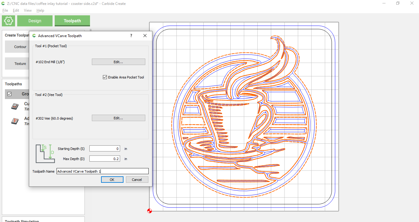
Step 8: Create the advanced Vcarve path
This time we select the border as well as the design, since we want to pocket the inverse of the design


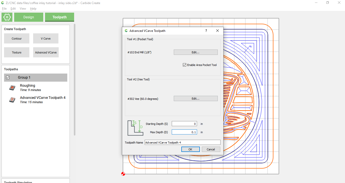
Key here is to make the depth to be 0.1" (and not 0.2" as before)

Step 9: Saving gcode
Save the cutout and roughing GCode separate from the Advanced VCarve toolpath by enabling/disabling the toolpaths

The following steps are about cutting the designs out with the Shapeoko.

Step 10: Machining the base design

There is nothing special about machining the base design, zero as normal on the bottom left corner, and cut out the base:

Step 11: Roughing phase for the plug

For the plug, before starting the roughing pass, zero as normal to the bottom left corner / top of the material, and run the gcode for the roughing and cutout steps

Step 12: The magic happens here

At the end of the roughing pass, we need to do some tricky steps. It’s important to NOT rezero at this point, but to follow these steps instead.

In the “MDI” screen of Carbide Motion, run the GCODE command “G0 X0 Y0 Z10”:


This will move the cutter to your zero point, but 10mm above the material

Then go to the “Jog” screen, to the “Zero” subscreen:


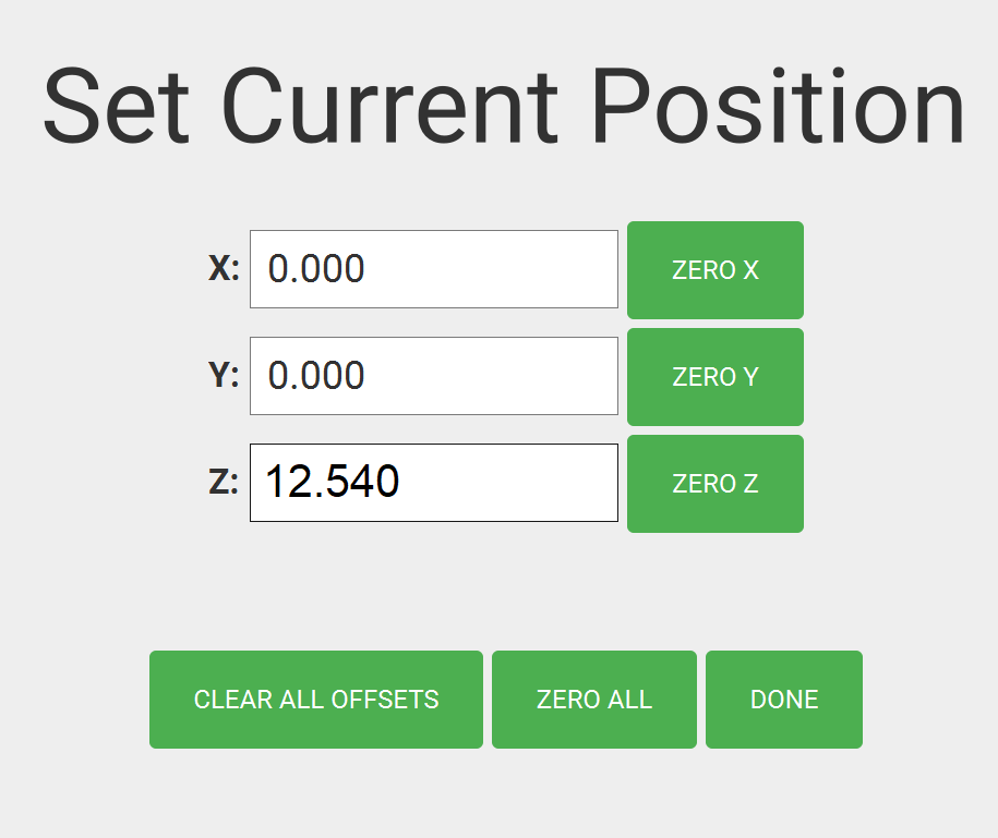
and here we manually replace in the “Z:” field the value of “10.000” with “12.540”.
(if you see inches here, add 0.1" to the Z field)

Step 13: Run the vcarve toolpath

Now you can run the vcarve gcode for the plug. Important: In Carbide Motion, use the speed buttons to reduce the speed from 100% to 50% since there’s going to be some deeper-than-normal depth of cut cutting going to happen.

Step 14: Clean-and-glue
I used a toothbrush to clean the fuzz/dust out of both designs, and then applied glue on the base and used a small brush to make sure the glue is in all little nooks and crannies. Then I put the plug in and clamped the two parts together.

Step 15: Saw, Cut or Sand the top off:
After the glue is dry, you can use a bandsaw to cut the top off, or use your CNC machine to get rid of most of the excess… and then sand it down smooth

22 Likes

Could you explain the purpose of the MDI setting Z to 12.54? It’s not clear (newbie) what you are trying to achieve by doing this - eager to learn :slight_smile:

well the short answer is trying to get a 0.1" Z offset.
to explain why I want that I need to make a diagram, I’ll try that later today

3 Likes

I’m tracking that you are manually lowering the z. I was thinking you needed to raise the z so that you would create a flat top on the plug for glue space. But the part that I’m confused about is getting the v bit to cut the opposite side of the line and create a peak to fit into the valley. By just pocketing the other side of the line you’re not creating the matching side. I feel like you need to explain the offset and geometry selection a bit more. I’m thinking the start depth on the main piece needs to be set to .1 and the max depth set to .2… and the plug start depth set to -.1 and a max depth of .1 would be easier than messing with manual z adjustments.

I’ll try to explain, but I’m not a good teacher so if I miss something or am unclear please ask questions

The geometry I’m going to use as example would be a simple square in carbide create; more complicated geometries all work the same but for the explanation, simpler is better. In the pictures below I’m going to look at it from the side of the wood, so “up down” is the Z axis and “left right” is the X axis; I’m going to ignore the Y axis entirely and assume that I’m looking at this somewhere in the middle of the square.

if you look at this from the side, the stock would look like this:

drawing1

The two red circles denote where we have drawn the square in Carbide Create.
The total height of the stock here is 0.25"

now if we go cut this with a V bit (yellow in the picture) and cut 0.2" deep using a normal advanced vcarve path and cut the inside of our square, it will look like this:

drawing2

Now we’re going to the plug side of things. We flip horizonal (but hey it’s a square)
If we were to cut an advanced vcarve path on the outside of this square, it would then look like this:

drawing3

Again the red circles are where the lines of the square are.
This is not going to fit… the widest part of the base and the smallest part of the plug are the same size:

drawing3a

Now, the magic. We’re going to lower the bit 0.1"
Color wise the stock would then look like

drawing4
where I’ve made the top 0.1" of the stock pink and the bottom 0.15" the same brown as before for the plug.

Now if we do the cut, the result will look like this… and key is the pink colored part of the wood. This is the part of the wood that will go into the base.

drawing5
This is the key drawing. The red circles still denote the design in carbide create, and the red circle in this diagram will match up exactly with the red circles in the base diagram. The geometry in the pink part of the wood is the key, this will taper “inverse”, e.g. go narrower relative to these red circles, and that will make them fit into the base!

If you flip this around, and I’ve added the base back in it will look like this:

drawing6
a perfect fit! and there’s room below for glue to go

19 Likes

You should mention that the 0.1" for “glue to go” (for illustrative purposes) is going to make a really hollow space in the real world. You can even hear it echo in thinner materials.

So, best practice is to minimize the glue space as much as is possible. Sometimes this is a guessing game.

@fenrus +1 on the teaching!

5 Likes

yep I’ve edited the tutorial to add this

2 Likes

Does this make any permanent changes to the system setting of the machine that need to be reversed after the process is complete? Or are these settings simply changed when I re-zero the machine using my probe?

I get entirely how you’re describing this process to work and I understand fully how the vcarve inlay technique is supposed to work, but I am surprised it’s this complicated to actually make it work. In VCarve pro it seems so much simpler from what I’ve researched. Is that just because it’s an expensive paid for program and this is not?

this change is just a temporary tweak to where the zero is… next time you zero the machine to any piece of stock it’s completely reset again.

Carbide Create is maybe 1 feature away (allowing vertical offset on advanced vcarve) from making half the steps not needed… maybe we can convince @robgrz to add this to carbide create

3 Likes

Ok I was thinking it was damn close! Yea one little tweak in the very easy to use UI would make this super easy. I’m going to try your guide this week and I’ll try to remember to post my results. I was hesitant because I wasnt sure if it was a permanent change, but being that its not, its a no brainer to try. Thanks!

Thank you for the illustrations. Why wouldn’t increasing the depth of the vee cut on the inlay piece have the same affect?

image

you’re not going to get the right geometry that way… depth of cut does not change where the “red circles” of the design are.

you can do inset/outset kind of operations but that does not always work quite right

1 Like

Thank you. I will give it a try tonight.

I must have something wrong. When I jog to the XY0 Z10 position and change the the Z value to 12.54 as the new zero and then run the the cutter is staying above the workpiece, not diving into it deeper. I am just moving air, not cutting wood.

After jogging to the XY0 Z10 position, I am clicking on the Jog tab. Then I enter 12.54 in the Z field replacing the 10.0 and clicking the ZERO Z button.

This seems to be setting my zero now 12mm above the piece.

Figured it out. Don’t click the ZERO Z button and you are in business.

don’t click the zero Z button… just make the field say 12.54

1 Like

I have a question about step 12. When you go to the MIDI screen and Jog screens, how do you resume execution of the gcode? The program seems to stop when I click “remain paused” and run these steps.

ok maybe I need to clarify that; I made separate gcode files for the before and after of that

Oh ok. Thank you. That helps. I was editing out my Gcode files to resume with the vee bit carving step, but I thought that I might be doing it wrong.

I’ll tweak this bit to clarify