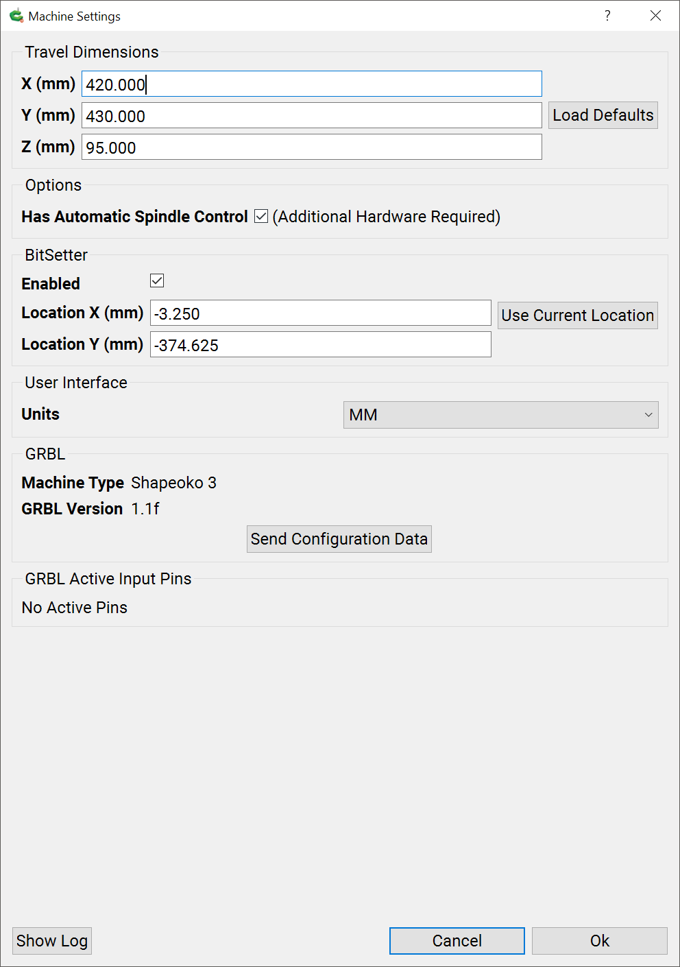
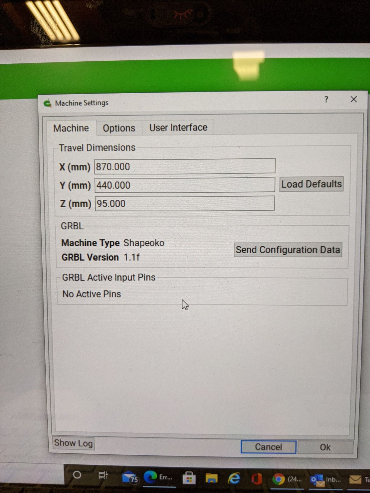
after which selection the Travel Dimensions for the selections made are entered into the dialog and will be preserved if one clicks “Ok” (and of course that change discarded if one selects “Cancel”).
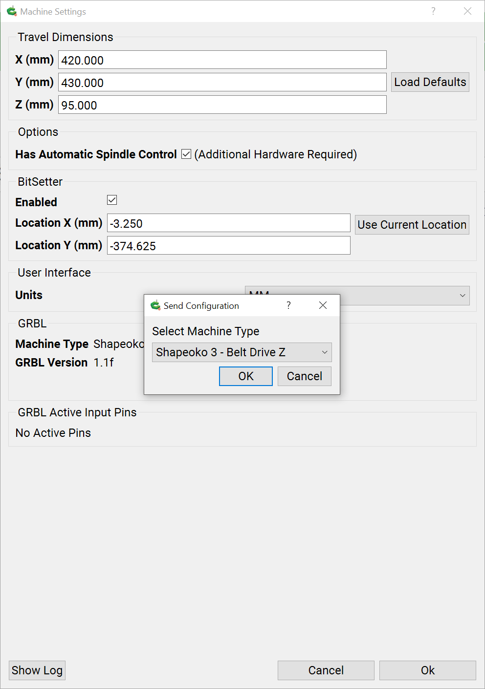
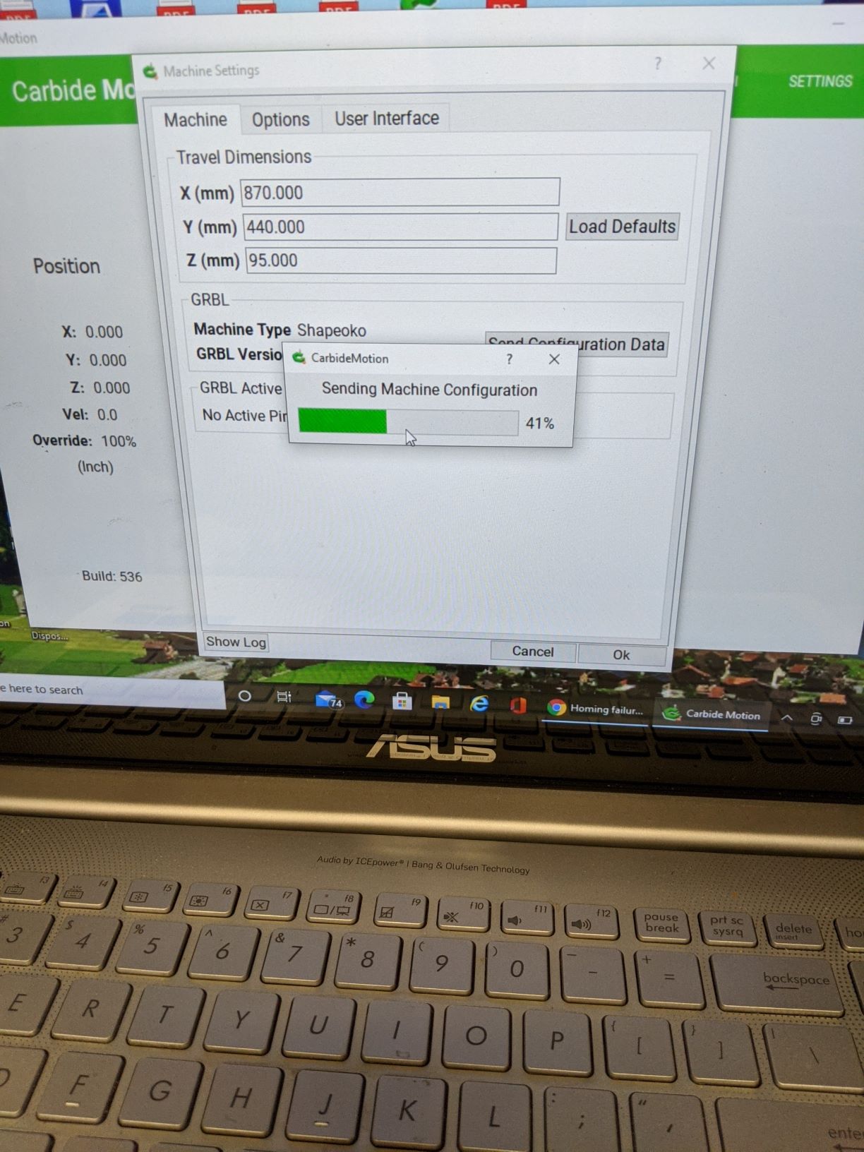
In addition there is a “Send Configuration Data” which actually sends settings to Grbl (the Travel Dimensions are for Carbide Motion to use for features such as Rapid Position). Pressing it brings up another window where one may select first machine type:
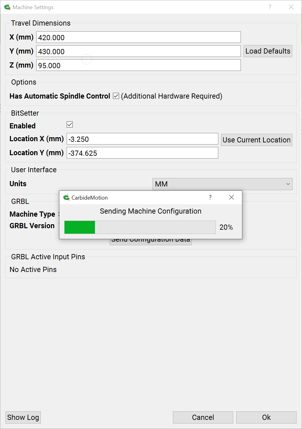
Since it is sent to the EEPROM on the machine’s control board, Canceling out of the dialog will not undo any changes.
It is important that the selections made for the two sections be consistent — one wouldn’t want the machine bottoming out if an HDZ is selected for instance.
I have downloaded 5.17 and am currently on 5.13, the configuration on the eeprom would still be set from the 5.13. So is it necessary to resend the config just because you upgrade to 5.17? From what I see above if you resend the configuration the HDZ must be set to 140 but otherwise when you pick your size of machine the other parameters are automatically set? I will most likely upgrade tomorrow after I see the answers. Thanks
No, the EEPROM configuration is persistent, and once it has been set for a given machine using a series 500 build of Carbide Motion should be fine and doesn’t need to be updated.
I was about to ask why the screens were so different between the installation guide for the BitSetter and reality, then realised I was still using 5.17 rather than 5.13 (which I’d decided to revert to), but you’ve explained it perfectly, thank you.
Can you tell me what the dimensions will be in order to have the same configuration of what was previously listed as hdz reduced x travel (ball screw) for those of us with a pwncnc boot?
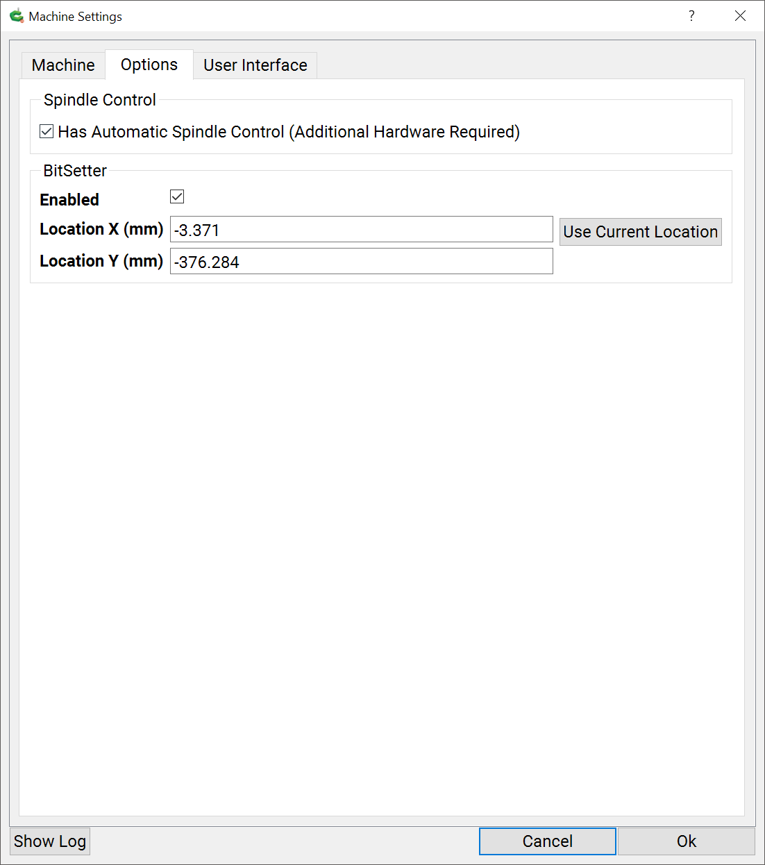
This is what i see on my machine settings page. i selected machine type Shapeoko Pro XL but there is no drop down for z-axis type.
should i have selected Shakeoko 3 - Z Plus instead even though i have a Pro?
ok it sounds like i have it configured correctly but still have homing failure starting with the Z axis with a loud grinding sound and spindle just shakes a bit and goes up and down slowly and then stops.
is it a mechanical issue?
when i swapped the z with x the z moved to the right stopped at the limit switch and made a vibrating noise but didnt pull off. noise stopped after about 5 seconds.
The motor is acting like it is running on one phase. Go thru the wire harness connector by connector from the motor to the control board. Push pull and wiggle on each of the wires looking for one that is loose, not seated, or broken.
Searches for “shapeoko 4 XL carbide motion travel dimensions” lead to this article. Is the Shapeoko 4 included in the dimension table posted above, and if so which lines?
When selecting a default for Shapeoko 4 XL/XXL in Carbide Motion it does change the XYZ values, but on my XL even with the app-provided defaults the machine runs past the max travel when performing rapid movements.
In various versions of CM they have changed the maximum travel dimensions for various models. A few of the versions they got the travel dimensions wrong and would correct them in the next versions. On many models they limit X travel to accommodate the Suckit dust boots that have parts that stick out beyond the sides of the Z carriage.
So if you want to figure out the maximum safe distance use this to figure out the dimensions.
In crease the current distances in the configuration.
Initialize
Start with t he X and jog your machine to the left side but try not to bump into the Y rail.
Set the X zero
Jog to the right until you almost hit the y rail.
Record that reading because that is your maximum X travel.
Now jog to the back of the machine until you almost hit the mechanical stops.
Zero Y and jog to the front of the machine past your BitSetter but short of the mechanical stops.
Record your distance and that is your maximum Y travel.
Jog your Z axis up to the top of its limit. Move the Z axis off the front of the machine so you do not crash the Z axis into the spoil board and zero the Z axis.
Now jog the Z down until you get to a level just below the top of the spoil board.
Record the distance and that is t he maximum Z travel. Some Z axis like the Z Plus may not mechanically travel as low as you may want due to their design.
Use the 3 maximum distances to set your own configuration.
The configuration settings in CM only effect jogging. When jogging the Shapeoko will not allow you to jog past the dimensions set in the configuration. However gcode can send the machine crashing into the physical limits. Gcode tries to go where it is told and ignores the physical and configuration limits imposed by CM.
CM is more than a gcode sender. CM understands the Shapeoko/Nomad machines and works with their features and limitations. 3rd party gcode senders can be configured to understand the Shapeoko/Nomad but are simply gcode senders and not necessarily good at figuring out the features and functions of a Shapeoko/Nomad.